Hi,
I need to verify the expansion joint highlighted in the figure according to TEMA RCB-8 Flexible Shell Elements 10th Ed. and I have some doubts.
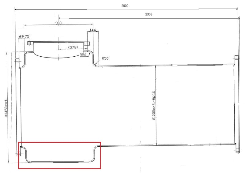
First of all, what unit of measurement should I use? I have noticed that many formulas give inconsistent results while substituting each parameter due to multiplicative coefficients (such as equation 3.6*sqrt(G*ts)). In what unit should I get the spring rate, the axial force etc.?
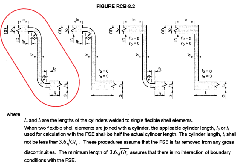
I modeled the joint according to Figure RCB-8.2 and I didn't quite understand what lengths I should assign to the cylinders (lo and there in the figure). Does "G" refer to the inside diameter or the radius? The shell thickness is 13 mm.
TEMA-8.3.2 says "The FEA model of the FSE shall be modeled using half-length symmetry, as shown in Figure RCB-8.3.2. As long as the shell length between the FSE and either tubesheet is greater than required by RCB-8.2, it may be modeled as being centered on the half-length centerline, regardless of its exact location. The modeled length (!model) shall be: lmodel=L/2 where L=length of the shell between the inside faces of the tubesheets".
How do I deal with the length to model "l_model" and "l_imodel" considering the straight part between the expansion joint?
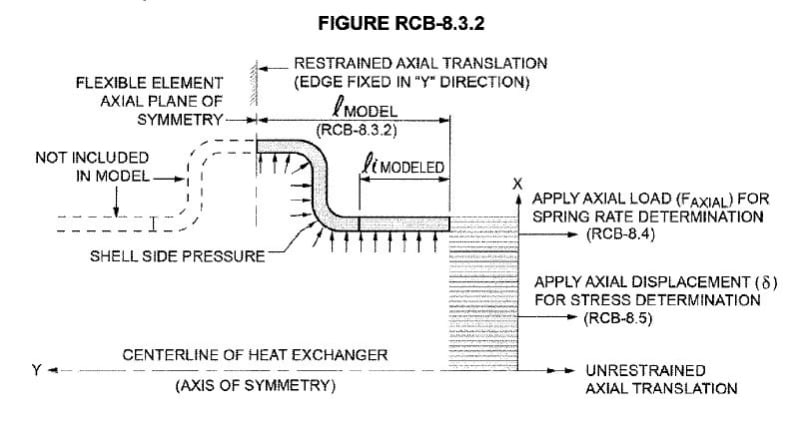
Regarding the boundary conditions "The small diameter end shall be UNrestrained in the axial direction" should I leave it free or insert a roller?
Regarding the figure RCB-8.3.2 "One modeling technique to apply axial loads and displacements is to construct a solid end cap as shown in figure" how can I build the "solid end cap" with SolidWorks Simulation (I am doing a 2D simulation according to RCB-8.3.3. Also for RCB-8.4 (Determination of spring rate) the axial force to be applied results to me 823 550 N considering "G" in mm (1024 if it is the diameter and not the radius). The formula is: Faxial=pi/4*G^2*1000 kPa (or 1 MPa to simplify mm). Is it correct?
Also, to determine the spring rate should I apply only Faxial or also shell inside pressure? Because sequentially from the explanation it seems that it has to be applied successively for the stresses determination (TEMA RCB-8.5), after the tubesheet analysis (RCB-7).
Thanks for your help.
I need to verify the expansion joint highlighted in the figure according to TEMA RCB-8 Flexible Shell Elements 10th Ed. and I have some doubts.
First of all, what unit of measurement should I use? I have noticed that many formulas give inconsistent results while substituting each parameter due to multiplicative coefficients (such as equation 3.6*sqrt(G*ts)). In what unit should I get the spring rate, the axial force etc.?
I modeled the joint according to Figure RCB-8.2 and I didn't quite understand what lengths I should assign to the cylinders (lo and there in the figure). Does "G" refer to the inside diameter or the radius? The shell thickness is 13 mm.
TEMA-8.3.2 says "The FEA model of the FSE shall be modeled using half-length symmetry, as shown in Figure RCB-8.3.2. As long as the shell length between the FSE and either tubesheet is greater than required by RCB-8.2, it may be modeled as being centered on the half-length centerline, regardless of its exact location. The modeled length (!model) shall be: lmodel=L/2 where L=length of the shell between the inside faces of the tubesheets".
How do I deal with the length to model "l_model" and "l_imodel" considering the straight part between the expansion joint?
Regarding the boundary conditions "The small diameter end shall be UNrestrained in the axial direction" should I leave it free or insert a roller?
Regarding the figure RCB-8.3.2 "One modeling technique to apply axial loads and displacements is to construct a solid end cap as shown in figure" how can I build the "solid end cap" with SolidWorks Simulation (I am doing a 2D simulation according to RCB-8.3.3. Also for RCB-8.4 (Determination of spring rate) the axial force to be applied results to me 823 550 N considering "G" in mm (1024 if it is the diameter and not the radius). The formula is: Faxial=pi/4*G^2*1000 kPa (or 1 MPa to simplify mm). Is it correct?
Also, to determine the spring rate should I apply only Faxial or also shell inside pressure? Because sequentially from the explanation it seems that it has to be applied successively for the stresses determination (TEMA RCB-8.5), after the tubesheet analysis (RCB-7).
Thanks for your help.