Hello Everyone,
I am currently designing a TEMA type DEU (or CEU) Heat Exchanger and am encountering some challenges, particularly regarding the simulation of the shell-to-tubesheet connection.
Below are the key design conditions for the heat exchanger:
I am currently designing a TEMA type DEU (or CEU) Heat Exchanger and am encountering some challenges, particularly regarding the simulation of the shell-to-tubesheet connection.
Below are the key design conditions for the heat exchanger:
- Design Code: ASME VIII-1 Ed. 2023
- Design Pressure SS / TS: 85.5 barg + FV / 125 barg + FV
- Design Temperature SS / TS: 190 °C / 390 °C
- Shell Course: ASME SA-516 Gr.70 + WO SA-240 321
- Shell Girth Flanges: ASME SA-765 Gr.2 + WO SS 347
- Channel + Tubesheet:
- Option 1: ASME SA-765 Gr.2 + WO 347
- Option 2: ASME SA-182 F321
- Exchanger Tubes: SAF 625 (Strength expanded and strength welded)
- Tubesheet Bolts: The original drawing specifies 2 3/8" bolts, a size not typically found in the TEMA standard. Is this size characteristic for such applications, despite not being under the TEMA standard?
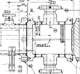
- Shell Girth Flange to Tubesheet Connection (DEU Type): The connection uses captive bolts within the tubesheet. However, for a DEU type, the channel typically does not feature an extended tubesheet configuration where the channel's outer diameter is smaller than the tubesheet's. Could this pose a simulation challenge? I'm finding it difficult to accurately model the tubesheet and the interface between its outer portion and the shell girth flange. Do you have any experience with this kind of TEMA Type? Does this configuration meet the DEU type definition?
- CEU Type Design (Extended Tubesheet): If I consider a TEMA CEU type design, I can have an an extended tubesheet (configuration e, ASME VIII-2), but typically with through-bolts (not captive). The code provides calculations only for the extended portion. I suspect this simulation might not be fully realistic. Perhaps it would be more accurate to treat the extended portion of the tubesheet as an "integral flange" (even if this is a somewhat forced interpretation). Do you have experience with this type of heat exchanger? Would through-bolts be preferable to captive bolts in this scenario? How might I best consider this kind of connection and interaction in the analysis?
- Temperature Difference & Material Compatibility: I am significantly concerned about the large temperature difference between the shell side (190 °C) and the tube side (390 °C). Furthermore, in the second channel configuration (with SA-182 F321 Integral as tubesheet/channel material), there is also a notable difference in materials between major components (e.g., carbon steel shell vs. stainless steel channel/tubesheet/tubes). How do these factors impact thermal stresses and potential issues like differential expansion? What design considerations or mitigation strategies should be prioritized here?
- Nozzle Self-Reinforcement: In several high-pressure designs (like this one), nozzles are made with butt-welded self-reinforcement. Is this a mandatory requirement or merely a common practice driven by experience and conservative design principles? Do you have any advice on this?
- Diaphragm Gasket: Is there any way to avoid the use of a diaphragm gasket in this specific design, and if so, what are the potential implications or alternative solutions?
- Design Improvement: Lastly, are there any ways to improve this heat exchanger design, perhaps in terms of efficiency or cost, given the current specifications?
Attachments
Last edited: