Continue to Site

Eng-Tips is the largest engineering community on the Internet

Intelligent Work Forums for Engineering Professionals

  • Congratulations waross on being selected by the Eng-Tips community for having the most helpful posts in the forums last week. Way to Go!

Tear out capacity of steel plate with holes? 1

Status
Not open for further replies.

psychedomination

Structural
Jan 21, 2016
123
Hi there,

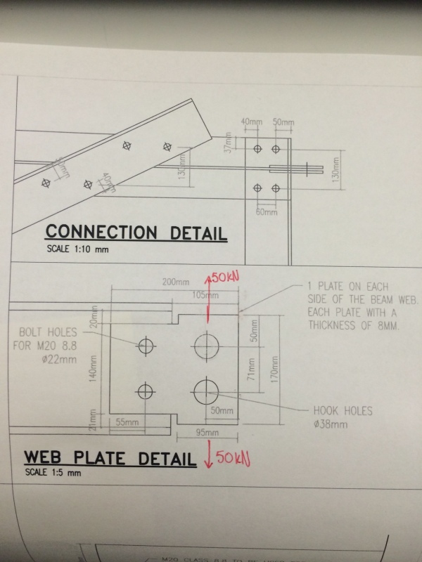
I am trying to determine if this connection is adequate for the loads that are applied. There is a 50kN force acting on the steel plate in opposite directions in the y axis.

The main fear was that the hook holes were too close to the edge and that they would tear through the end of the steel plate. Either a hook or shackle will be connected to the hole.

I originally did the following calculation but am unsure if it is adequate.

Effective shear area in the plane (thickness of plate * distance from edge of hole to end of plate) * Shear stress of steel ... taking the shear stress of steel as 0.6* yield stress
(50-38/2)* 16* 150 = 74.4 kN. ... Therefore would be OK.

However, I am not confident. Any advice on the calculations would be greatly appreciated.

image_x4vbpj.jpg
 
Replies continue below

Recommended for you

psychedomination, that is a very conservative but acceptable method. However for lifting equipment FOS is more often 4 - 5, I believe. You are apparently about 1 1/2?

I believe ASME BTH-1 has some useful guidance.

Regards,

Mike

The problem with sloppy work is that the supply FAR EXCEEDS the demand
 
The original equation above implies the stress across the holes of only one plate are being checked against a (50-38 KN force).
But the detail requires 2x plates - isn't the final stress halved?
The detail does not have a plan view: Are not the two 8 mm plates separated by the thickness of the WF web? If so, then add a third plate (of thickness = webb Th) and use that mid-plate to prevent bending also.
 
@SnTMan I appreciate the reply. I will look into less conservative approaches as a means of cost saving in the future.

@racookpe1978 I believe that is somewhat true. However I used a thickness of 16mm (the total of the two plates) so would've ended up at the same answer. On another note in the equation the 50-38 is not a range of forces in kN it is a measurement in mm considering the diameter of the hole (38mm) and the distance from the center of the hole to the end of the plate (50mm)

There is a plan view of the detail, albeit quite small. It is shown in the 'connection detail' diagram shown above. There is an 8mm gap width between the two plates due to the web thickness. The gap length is 105mm. Should this be a cause for concern?
 
Psychedomination:
I assume this problem is a continuation, a corner detail, of your earlier OP’s/threads, on a container lifting frame. If you are still using 50kN as a max. corner load, it would seem that you have not paid much attention to some of the earlier comments and suggestions, by some of the other earlier contributors/posters. That corner load should be more than a quarter of the total load, probably at least TL/3. It would also seem that you haven’t bothered to get and read copies of ASME BTH-1, or other comparable documents. They are really important documents/guides for what you are doing. Look for the design of pin plates for this particular detail, but study the whole of the documents. There is much more to consider than just the shear stress (actually it’s a tensile stress on the net section) that you have looked at. The 38mm holes look like a strange dia. selection; they are too small for most hooks and too large for reasonably sized shackles. You should pick the proper shackle size and then make all of the shackles a permanent part of this lifting frame. And, then the shackle holes should only be about 3-4mm larger than the shackle pin dia. I agree with Racookpe1978 in saying that there should be a filler pl. the same thickness as the beam web, and you say that’s 8mm. I disagree with him, given your current double pl. arrangement; in that there is a significant likelihood that the shackle load could be applied to only one of the two pls., and you should design for that. Those two thin pls. are also more likely to buckle. Your two 8mm side pls. are too thin. The sum of the three pls. should be just a little less than the shackle throat width, at the pins, and the three pls. should be welded together at their perimeters so they act in unison. There isn’t much “cost saving in the future” in this detail, one way or another, but it does have to be done right; to be strong enough and cleanly detailed for fatigue and abuse life. I would be inclined to cope the beam flanges, and do a good job of cleaning them up, and then add two side pls. to make up the proper total width. Then weld the side pls. to the beam web, all around. Finally, drill the holes through all three pls. and clean them up, with a nice radius on the hole edges. I don’t particularly like the idea that this lifting frame appears to be bolted together. That’s just another thing that can loosen, and must be inspected frequently.
 
Thank you for the reply @dhengr I very much appreciate your insight and experience on this matter. I agree that my factor of safety was quite low for these connections, using only a factor of safety of 1.5. I will look into this. I also agree that a filler plate in between will be ideal. I assume that this will also help to prevent the exterior plates from buckling. You say that the side plates are too thin at 8mm; they are quite thin, however, the reason that I chose the 8mm thickness was because I felt that they needed to match the thickness of the web. If the plate and web thickness did not match (i.e. the plate thickness was higher), the web thickness would've been critical and failed first regardless of if the side plates were thicker or not (this is my understanding, correct me if I am wrong). The main reason I chose to bolt this frame instead of welding it is because this will be done on site and bolting would be easier. In the country that I live in quality control of the welds would be an issue. I did plan on coping the flanges of the beam at first, however, the beams come in standard lengths of 20' and I needed an extra 200mm or so if I coped the beam, which is why I added that extra distance as plates on the ends.
 
Status
Not open for further replies.

Part and Inventory Search

Sponsor