Note: this thread may start and stop periodically as I see people’s comments and then see if I have other needs for input.
From a prior thread, the topic of Load Paths (LP) came up. I tried to recall when I first heard of them and started practicing tracing them. I arrived at the BS degree level did not teach them and none of my BS level textbooks even have a reference to them. I do recall hearing of them while taking my Master’s. I looked online and found some instructional videos and watched 2 or 3. One was an hour long from a university lecture. The structures in that video were more complex than you get in a BS degree so I assume it was a Grad level course. One was a skyscraper with floors that cantilevered back to a “central” core for stability. Big, but not complicated in terms of load paths. The other 2 videos had very simple and symmetric structures they traced. Since I feel LPs are important for students to understand early in their training, it started me thinkng about them.
I tried to think of how I would explain LPs to a Junior level BS student. I arrived at the basic definition of a LP that I use is somewhat common for experienced engineers, but it can be confusing to students. I intend to keep using it in the future, but not when explaining to novices on the subject.
For both experienced engineers and students, I am interested in what your definition of load paths is and when you recall first hearing of them. I am also curious what answers you get to the following 2 Free-Body Diagrams if you applied your definition to the task. While these 2 are simple for experienced engineers, they are more complex than the examples used in the videos I watched.
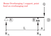
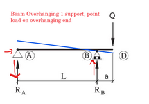
The first is a Simple Span Beam.
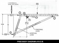
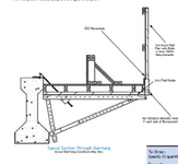
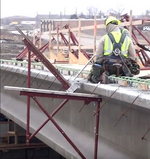
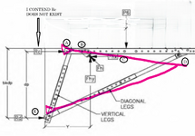
The second is a Bridge Bracket used on new bridge construction to form and pour the outer overhang such as gutter and guardrail areas. Note that I do not think reaction Rc is truly present and definitely not present on downward arm loads. The bracket has a single point load called P6. Trace the paths based on the letters shown at the joints and load application. Points B and E are the only 2 places where the bracket either mechanically attaches (B) or bears against (E) the bridge girder.


![Load-path[Engineersdaily.com].png Load-path[Engineersdaily.com].png](https://www.eng-tips.com/data/attachments/15/15410-1996ad296edc929dcdfa853da667a619.jpg?hash=o0eF6-1syG)
