Continue to Site

Eng-Tips is the largest engineering community on the Internet

Intelligent Work Forums for Engineering Professionals

  • Congratulations cowski on being selected by the Eng-Tips community for having the most helpful posts in the forums last week. Way to Go!

T-wall design guidance

Status
Not open for further replies.

Guest090822

Structural
Jan 18, 2017
260
Does anyone know of a good resource that covers the design/analysis of T-walls?

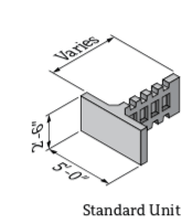
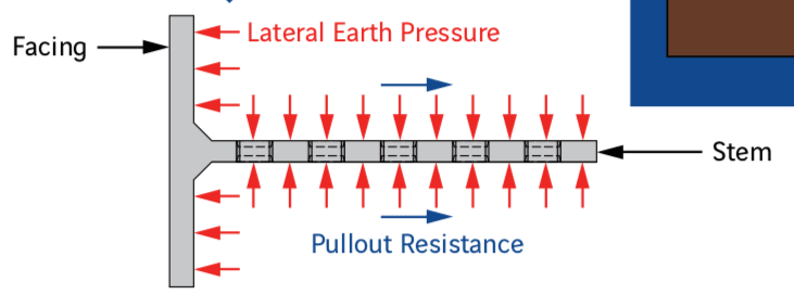
Here are a few screen shots since I know the first things engineers need is a sketch [bigsmile]:

Screen_Shot_2021-04-26_at_8.13.24_AM_t9hzor.png


Screen_Shot_2021-04-26_at_8.14.24_AM_gj3uxg.png
 
Replies continue below

Recommended for you

I had a project recently that used about 2000' of T-Wall. The wall was designed by Reinforced Earth Company. They gave us the stability calculations but not a design for individual pieces. The wall is a pre-qualified system by NYSDOT.

However, attached are their standard reinforcing details for the tees; perhaps it will help.
 
 https://files.engineering.com/getfile.aspx?folder=b1573e3a-b521-4cec-a74a-292f16ddcc85&file=T-Wall_Standard_Reinforcement_Drawings_.pdf
Bridgebuster - I’m actually more interested in the stability aspects. I’m not not finding much on how the pullout resistance is determined. These types of walls aren’t really handled by AASHTO.
 
bridgebuster - did that package also include the two other levels in the analysis? What you posted so far has helped greatly, but there are a few things I'm just not seeing and can't determine how they came up with the numbers. I think if I had the two other levels it may help.
 
TheRick109 - I’ll take another look to see if there’s anything else.
 
Bridgebuster - thanks for trying.

Steveh49 - the calculations Bridgebuster provided are very helpful, but there are a few portions I can’t make out.

PennDOT has an excellent T-wall package that gives some design philosophy, but it clearly isn’t the same as the calculations Bridgebuster provided.

I’m just surprised at the lack of design literature in these types of walls.

 
RECO do seem to be trying to keep their secrets in those calcs. I haven't tried to reproduce the numbers but think their pullout resistance is the sum of:

1) Friction on the vertical faces of the stem, at those little recesses where the friction plane is soil-soil.

2) Friction on the remainder of the stem away from the recesses: soil-concrete interface.

3) Friction on the horizontal interface between layers, or on the foundation for the bottom layer of tees.

A marketing brochure mentions the fill is compacted (obviously) but they may be taking quite high at-rest pressure in the calcs for 1 & 2 due to this.


Which PennDOT document are you referring to?
 
See attached.

They give some design information, but it clearly isn't the same as what the calculations that Bridgebuster provided follows. I've been able to decipher a lot more than I did last week, but I'm still off on a few things.

I understand the concept now, but again, I can't verify the calculations - mainly on the pullout resistance. Everything else is pretty straight forward.
 
 https://files.engineering.com/getfile.aspx?folder=e7b69a21-b591-4aba-952d-72252189cae1&file=NP60.pdf
Status
Not open for further replies.

Part and Inventory Search

Sponsor