I took a few minutes to run through this in the fashion I eluded to above.
1) I made a quick assembly consisting of two tubing connections, mated where I wanted them to be for this example (5 inches apart vertically and horizontally, but sharing a center plane). See Image ASSY1.
2) Select Insert >> Component >> New Part. Click in empty space on the screen. This adds a new part to your assembly tree. Right click the new part, click "Rename" and name it something you want, I named mine "TUBING". Right click again and "Save Part (in external file)" and select where to save the model. See image ASSY2.
3) Right click the new part and click "Edit Part" to being editing the new component. Your existing parts in the assembly will go transparent. I like to turn on any sketches from existing components in the assembly that I can use as reference lines. In this case, I turned the sketches on visible for both tubing connections. See image ASSY3.
4) Start a new sketch on whatever plane is your aligned center for both parts. In order to use the existing sketches as reference, I like to use the Convert Entities tool to make the sketches usable relations in the current sketch. In this case, I used the Convert Entities tool and selected the center lines of both tubing connections. This makes them usable lines in my new sketch. See image ASSY4.
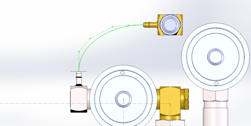
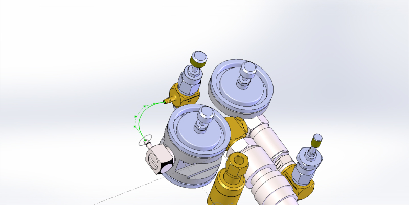
5) Now, on the center plane I draw my sweep path that I want my tubing to take, mating it to the converted center lines from the other two parts. See image ASSY5.
6) Now I sketch the profile on the plane that I want, ensuring the center point of my profile is on the path line. See image ASSY6.
7) Now I simply use the Swept Boss tool to make the sweep. See image ASSY7.
8) Once complete, exit the part editing mode just like you would edit the sketch. See ASSY8.
The good thing about this, is that if I change the distances of the tubing connections and where they are mated, the tubing will automatically update and follow, since I mated the sketch to those two parts.
-E
M.E.