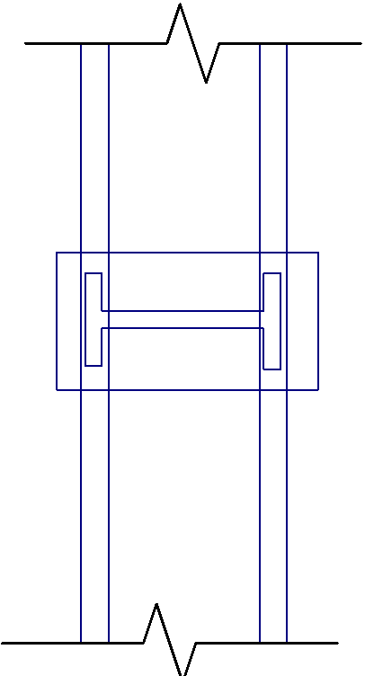
I think if one or both of the flanges don't align, then its a pretty poor detail. If one flange aligns, all the force would tend to go to this flange as the stiffest element, the forces follow the stiffness. A simply check on the plate in either case would be to assume the plate is simply supported between the column flanges with two point loads for the forces in the flanges applied and assume a yieldline on the outer edge of the flanges. If there was a large offset in alignment, I'd imagine quite a thick plate might be required as you are reliant on bending the plate about its weakest axis.
So there is no plate opposite the web on the column? If it failed certainly looking at putting a plate in alignment with the web of the brace welded into the column flanges/web would be an option to improve the load path.
If the flanges don't align, carefully consider how the load from the plate goes to the inside face of the column flange weld if its not a full penetration weld between the plate and the column flange. This location potentially sees all of the shear in the plate + forces from trying to resolve any moment in the plate between any fillet welds either side of the column flange. I'd expect it would need to be a CJP weld also between the plate and the column flange for this reason, least I'd detail it that way so the weld is not the limiting factor in trasferring loads around the plate/column interface.
For tension and compression capacity of the plate for the aligned flanges case, work out the bearing area and multiply by the yield stress of the plate and any other code reduction factors to give you the capacity. Do the similar exercise between the plate and the column flange.
You can spread out the load as it travels though the plate, its usual in steel 'bearing' checks to allow something like a 1:1 to 1:2.5 spread depending on the code/situation. Check your code equations for bearing of forces on the flanges of beams (yielding or crippling of the web) and how this load is allowed to be spread through the flange or perhaps any code or design guidance on force spreading out through base-plates to determine a bearing area at the underside of the base-plate. Just adopt a similar philosophy for any of your checks.
I've always been taught to try and avoid placing major loads across the through thickness of the plate due to lamellar tearing issues (in thicker plate at least). I understand that the restraint due to welding shrinkage, can also be an issue causing additional stresses/fracture through the thickness of plates.


