Tek-Tips is the largest IT community on the Internet today!

Members share and learn making Tek-Tips Forums the best source of peer-reviewed technical information on the Internet!

  • Congratulations cowski on being selected by the Eng-Tips community for having the most helpful posts in the forums last week. Way to Go!

Structure Design in Catia or?

  • Thread starter Thread starter Kristian Mueller1
  • Start date Start date
K

Kristian Mueller1

Guest
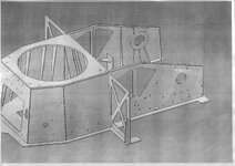
View attachment 1678Hello, i have pictures of complete Catia model of part of armored vechile. That is not my work. But i dont now how that structure modeling in Catia, with structure design or part by part and then assembly together? Have for this "easy way" modeling with structure or sheet metal? Please give me short instructions for modeling and steps. Thanks.
 

Attachments

  • 11.jpg
    11.jpg
    431 KB · Views: 8
There are several methods that could be used (or your company may have their own standard procedures), but based on the picture, I would use the Part Design and Assembly Design workbenches simultaneously to model this. An "easy way" would be to use contextual design techniques (sometimes called "skeleton") to design the parts relative to other parts in the context of the assembly.
 
Last edited:
Yes, thanks for answer, but that is "hard way". Have u some options for a structure design with metal panels? Then just ribs add afterward? I think maybee that is "easy way".
 
Sorry, but I'm not familiar with how to use the Structural Design tools in CATIA. I thought they were for I-Beams and structural steel members (columns and beams), but I guess they could be used for an armored tank also. Maybe someone else can help you.

I did find this tutorial that might help you get started: http://www.mech.upatras.gr/~papado/CAD/2012-Lab11_Structure Design.pdf
 
Thanks for answer, but i think that "easy way" is create a 2d dwg file in AutoCad and transfer to Catia and make 3d parts (just pad parts). And then assembly together. Shorter time for modeling.
 
This depends what licenses are available for you. If you have Structure Design and is fitting your needs, go with this license, is faster. If not, you can create some power copies and design tables in part design, create 3d parts in part design, then use assembly design to create the product, it will be far away faster then what you said.
 
Thanks for answer, yes i have booth. But AutoCad have many options to create 2D drawing, and is faster. Just put dwg/dwx file in Catia, close any open contuor with sketch analise and then Pad.
 
Another question is making rib (Stiffener) in Catia. For this have in Catia command Stiffener Definition. But, in my case my Stiffener have some parts (holders) in vertical plates. The question is have i use stiffener command to make this or modify in vertical plates, or use else command to make stiffener with holders?
 
Could you attach a picture of the stiffener, please.

Is the stiffener a sub-feature of the vertical plate?
 
Here is armored vechile drawing, u see vertical plates and many stiffeners. Can i this stiffeners make with classic command or draw individually, or modify stiffeners with classic comand, becose each stiffener have holders in vertical plates. Please help.:confused:View attachment 1680
 

Attachments

  • 11.jpg
    11.jpg
    431 KB · Views: 7
If you're using the Part Design workbench, you could use Stiffeners for all the gussets. Because of the shapes, I would make Pads. Either way will require a Sketch and a Plane.

What is the "classic command"?
 
Huh yes i think same, all stiffeners requere Sketch and Pad. Then assembly to vertical plates.Lots os work. :p
 
Why are you assembling? Are the stiffeners individual parts?
 
See picture. I think yes, all stiffener is individual and have holders.Holders is set in vertical plates. Try to draw some parts and send me to private mail. Lots of work.
 

Part and Inventory Search

Sponsor

Back
Top