Hi,
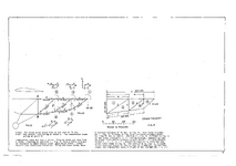
In the picture that follows, is fig 9 correct?
Using the scale in pounds shown there, the 70LBS line seems to be correct, where line a seems to be more or less 110 lbs and line b seems to be more or less 130 lbs, but using trigonometry I got something else for a and b.
So, is it possible to get a and b through trigonometry?
If you draw the line for the 70lbs according to the scale in pounds, how do you know where to stop when drawing a? or b? if you start from b.
I mean line a could be any length and fig 8 does not indicate how long line a should be.
What would be the best way to add the sketch of fig 8 together?
I really do not understand even how the 180 and 230 lbs are get.


