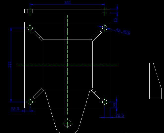
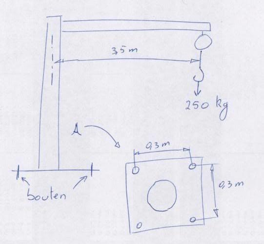
would like to fasten the frame (see attached drawing) to a concrete block.
But in my calculation, I don't need the height of the pillar. I am overlooking something. Can someone take a look at it, and tell me what I'm doing wrong?
btw, this is my responsability, this information I receive will not be used for anything that might result in personal injury.
Excuse my english, I'm european (belgium) hence the dimensions and weights are also in kg and meter.
My point of view: the weight at the hook will result in a momentum: 250 kg * 9.81 m/s² * 3.5m = 8600 Nm
Will this momentum result in a force at the two opposite bolts: F = 1/2 * 8600 / 0.3 = 14.333 N ?
Tensile area of a Metric 16 bolt = 157 mm²
stress in 1 bolt = 92 N/mm²
yield stress of such a bolt (grade 8.8) is 640 N/mm².
stress should be limited to about 1/3 of the yield stress (correct?), but still 92 N/mm² < 640/3 (213) N/mm², and I still have a safety factor of bigger than 2.
Can anyone tell me why I didn't use the height of the pillar? Where did I miss something?
attachment: