Tek-Tips is the largest IT community on the Internet today!

Members share and learn making Tek-Tips Forums the best source of peer-reviewed technical information on the Internet!

  • Congratulations MintJulep on being selected by the Eng-Tips community for having the most helpful posts in the forums last week. Way to Go!

Stirrups in 36” x 36” Concrete Beam

Status
Not open for further replies.

marinaman

Structural
Joined
Mar 28, 2009
Messages
195
Location
US
I’ve got a strange situation where I have a 36” x 36” concrete beam that is linking (4) concrete caissons together for a foundation.

I have a group of (4) caissons. The (4) caissons are spaced 10’ From each other, in each direction. To “tie” the (4) caissons to each other, I will need a 36” x 36” concrete beam to sit atop the caissons. The beam is this big simply due to geometric requirements....for example, I have (4) anchorbolts at each beam corner that require 28” embedments, the caissons are 36” diameter, and the caisson vertical reinforcing needs to be properly embedded into the concrete beam above.

I have a question about proper detailing of the closed ties for such a big beam. It seems odd to me that I just need to provide a closed tie around the perimeter and that be it. I’ve looked in my CRSI guides, ACI, and other places and do not see any other requirement. Should there be other ties, through the body of the beam, simply to meet some minimum tie requirement? I can’t find it if its required....but is there a best practice out there where I should do something like this?
 
 https://files.engineering.com/getfile.aspx?folder=8b2721aa-2b0e-452f-a60b-37a3a1072659&file=F1365717-11EE-41BA-B893-287E4B2C94DD.jpeg
Will the beams be in compression? If so, I would expect that you would need to tie them as per a column, in which case I would expect there would at least one intermediate tie.
 
As a tip: there's a requirement in european codes that the transversal distance between stirrups legs should not be higher than the height of a beam or 600mm (23").
 
and with CSA A23, there is a minimum stirrup requirement based on the depth and the width. Don't know if your code has a similar provision.

Dik
 
For bridge abutments and piers we do beams (caps) that size all the time; nothing unusual about it. Anyway, we would do those with single shear ties around the perimeter fairly commonly. If the ties are doubled up (2 ties at each location), then we would do narrower ties (approximately 2/3 of the width) and offset them.

The other thing we do, for ease of forming the cap beam and proper placement of the reinforcing, is make the cap width at least 3" wider than the caissons. We allow a 3" tolerance on the position of the caissons, so in order to make it easier to get all the vertical caisson steel inside the beam reinforcing cage, we give them some extra space. Even with exact placement of the caissons, the outside diameter of the vertical steel would be a tight (or impossible, depending on the size of the ties, the size of horizontal 'skin reinforcement', and the concrete cover) fit inside the horizontal steel on the sides of the beam.
 
The upper portion of caissons is above grade. You probably will be forming that portion with cylindrical cardboard forms (sonotubes). The four beams are actually a pile cap with a hole in the middle. The pile cap should project two or three inches beyond the caissons and should overlap two or three inches vertically. There is no need structurally to provide more ties than closed ties around the perimeter but you may want to provide additional ties for bar support.

BA
 
Your sketch shows the ties stopping at the edge of the piers. I would want them to continue through the corner area where your pier verticals and anchor bolts lap.
 
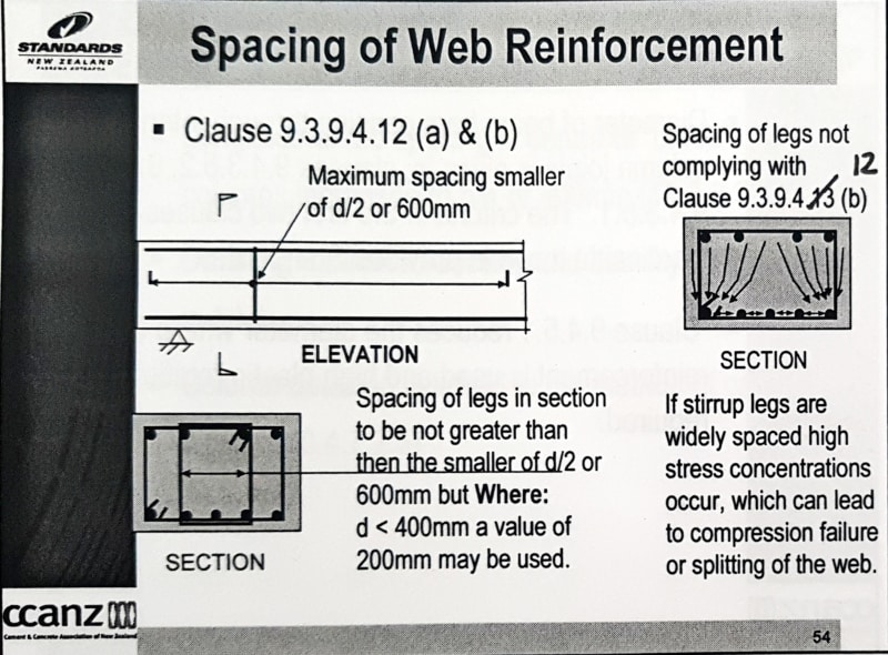
Our local code (NZS3101) also has a similar provision to that mentioned by others for spacing across the section, namely:-

Untitled_ceg6d8.png

Note d = effective depth

I'm surprised ACI doesn't/might not have something similar as a single perimeter stirrup is quite a poor configuration in wide members for the reasons noted below.

Specifically from clause R11.4.7 in ACI318-08:-
Untitled_dlomwy.png


The reason for distributing the shear legs across the section as far as I was aware was so that for the force to track to the reinforcement leg the force struts were close to vertical, otherwise for legs too far apart, the forces tracking to the shear legs are getting steeper and more horizontal. As such there is a horizontal tensile force across the bottom of the section to resolve the sloping struts from the uniform shear across the section. This horizontal component can lead to longitudinal splitting of the concrete along the section.


EDIT... picture of what I am describing
2018_09_14_13_25_Office_Lens_eivnj1.jpg


Another reason is often codes have provisions that every 'n'th bar on the compression face requires restraint for antibuckling requirements, or if the capacity of the beam member relies on the compression reinforcement to achieve its ultimate strength. Usually its every 2nd bar with those less than 150-200mm from a restrained bar being exempt. These requirements naturally lead to a distributed arrangement of shear legs when there are more than 2 bars in wider sections. I'm sure there is probably something similar in ACI318, its just a matter of finding it and interpreting it to your situation.
 
Another important issue is that having well distributed shear reinforcement across the section improves the aggregate interlock through reducing the size of cracks. When cracks open too far this reduces the effectiveness of the aggregate interlock and hence concrete component of the shear capacity.
 
Status
Not open for further replies.

Part and Inventory Search

Sponsor

Back
Top