sTRU_eNG89
Structural
thread507-328375
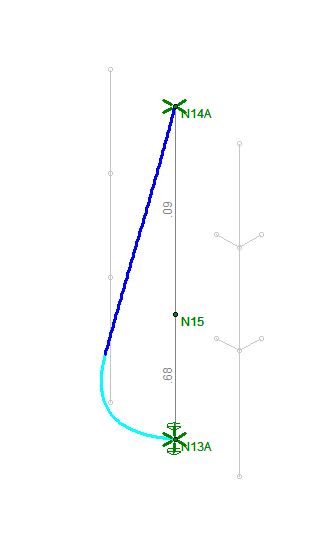
In the connected thread, the individual who posted the question is attempting to address a column that changes shape mid way up the building. Currently, In a project I am working on, I have a somewhat similar situation. We are creating a three story atrium space in the corner of a building, making the column in this corner un-braced for three stories, requiring reinforcement. The construction sequence requires the column be in a condition of reinforced for the upper two floors, while un-reinforced for the bottom third floor (15 ft floor to floor). Therefore, the column will be in a kind of 'reversed step column condition', where the bottom third of the three story span is significantly less stiff than the top two thirds.
I have done a decent bit of background research on step column design, but have come up dry for a formula or approach (other than Successive Approximations) for this kind of condition. While I believe the method of successive approximations will get me a result, it is very tedious. However, a response in the attached thread, by @WillisV's, presents a simple solution that I am curious about:
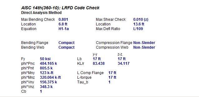
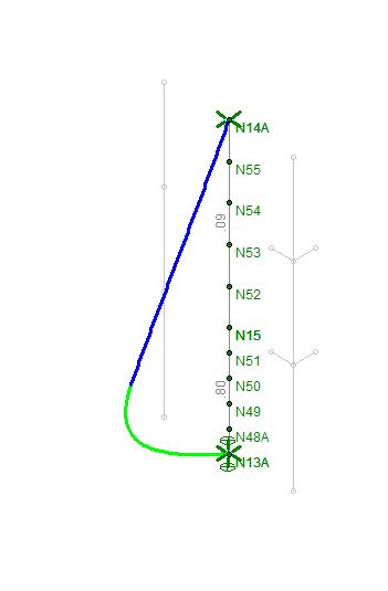
"Just analyze it with the direct analysis method. No issues with separate shapes. Model it with an initial sinewave bow equal to L/500, split it into several segments, reduce the stiffness, run a second order analysis - done."
However, I am a little confused how the separate shapes do not pose an issue in the second order analysis of this approach. Are the results of the second order analysis not dependent upon the stiffness and un-braced length of the column? If so, what is the stiffness of the column if the moment of inertia, "I", varies?
For example: If you input the two shapes (one 15ft long and one 30ft long) into RISA it will consider the unbranded lengths to be 15ft and 30ft, not the full 45ft. Providing inaccurate results. However, as an alternative, if you modeled a single, 45ft, column, how would you determine the needed "I" value for the second order analysis? Based on my research, it would appear that a weighted average of the "I" values is not adequate.
Is there something I am misunderstanding about the way in which a exact second order analysis is performed in computer programs?
Maybe there is something I do not understand about the DAM? I know that the DAM requires the reduction of the stiffness of the member by 20% (.8EI) to account for residual stresses and system imperfections. However, I am not aware that this stiffness reduction accounts for a non-prismatic member. If that is the case, can anyone provide sources that show that?
Thank you in advance for any assistance and clarification provided here.
In the connected thread, the individual who posted the question is attempting to address a column that changes shape mid way up the building. Currently, In a project I am working on, I have a somewhat similar situation. We are creating a three story atrium space in the corner of a building, making the column in this corner un-braced for three stories, requiring reinforcement. The construction sequence requires the column be in a condition of reinforced for the upper two floors, while un-reinforced for the bottom third floor (15 ft floor to floor). Therefore, the column will be in a kind of 'reversed step column condition', where the bottom third of the three story span is significantly less stiff than the top two thirds.
I have done a decent bit of background research on step column design, but have come up dry for a formula or approach (other than Successive Approximations) for this kind of condition. While I believe the method of successive approximations will get me a result, it is very tedious. However, a response in the attached thread, by @WillisV's, presents a simple solution that I am curious about:
"Just analyze it with the direct analysis method. No issues with separate shapes. Model it with an initial sinewave bow equal to L/500, split it into several segments, reduce the stiffness, run a second order analysis - done."
However, I am a little confused how the separate shapes do not pose an issue in the second order analysis of this approach. Are the results of the second order analysis not dependent upon the stiffness and un-braced length of the column? If so, what is the stiffness of the column if the moment of inertia, "I", varies?
For example: If you input the two shapes (one 15ft long and one 30ft long) into RISA it will consider the unbranded lengths to be 15ft and 30ft, not the full 45ft. Providing inaccurate results. However, as an alternative, if you modeled a single, 45ft, column, how would you determine the needed "I" value for the second order analysis? Based on my research, it would appear that a weighted average of the "I" values is not adequate.
Is there something I am misunderstanding about the way in which a exact second order analysis is performed in computer programs?
Maybe there is something I do not understand about the DAM? I know that the DAM requires the reduction of the stiffness of the member by 20% (.8EI) to account for residual stresses and system imperfections. However, I am not aware that this stiffness reduction accounts for a non-prismatic member. If that is the case, can anyone provide sources that show that?
Thank you in advance for any assistance and clarification provided here.