Continue to Site

Eng-Tips is the largest engineering community on the Internet

Intelligent Work Forums for Engineering Professionals

  • Congratulations cowski on being selected by the Eng-Tips community for having the most helpful posts in the forums last week. Way to Go!

Steel member embedded into RCC column/pedestal 1

Status
Not open for further replies.

NewbieInSE

Structural
Dec 19, 2019
234
Hello Dear Engineers,
This one seems to be pretty complex to me. We have a problem which I'm pretty confused about the load transfer mechanism from steel to the pedestal. Please see the following figure.
steel_into_concrete_zagb6c.png


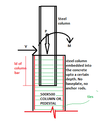
It would be great if you could give me some idea and a book/code reference on how to deal with such a problem. It is to note that, in this problem baseplate and bolts cannot be used.

Thanks for your spontaneous suppport.
 
Replies continue below

Recommended for you

I was thinking like this, but it is insufficient, I guess.
steel_into_concrete_hy5xqf.jpg
 
For bearing I would suggest having a base plate or welded studs. I would not want to rely on the webs/flanges alone for bearing. And there is no reliable friction.
For shear, it would be bearing from the column flange to concrete.
For moment, it would be a bearing-bearing couple between the column near the top of the pedestal and the bottom of of the column pushing the other direction. This is something of a back-stay effect and so it means that the net bearing at the top would be larger than your total applied shear. This also means that, generally speaking, deeper embedments are better for reducing this effect.
Key thing would be to make sure that you have sufficient cover for the development of shear reinforcing so that the shear load actually transfers from the steel into the concrete, otherwise it will just breakout.
 
Unless the loads are very small I would suggest you use a base plate and anchor rods... solves the problem of holding it vertical until the concrete cures and provides a more positive anchorage.

Rather than think climate change and the corona virus as science, think of it as the wrath of God. Feel any better?

-Dik
 
I'd recommend 'Composite Construction Design For Buildings' by: Viest, et al. (1997; published by: McGraw-Hill/ASCE). IIRC, it takes on a connection like this.
 
Tension resistance will not develop under the flange of the steel column.. The RC pedestal will resist the BM with horizontal bearing stresses ..

I will suggest you , use PC column pocket foundation model ..

pocket_oder_socket_i9xyml.jpg
 
Thanks all for your positive response. The mechanism is clear for me to understand now. Thanks to bobbyboucher & HTURKAK, the figure was helpful.

bobbyboucher and dik, it is an existing problem actually. The base plate and anchor bolts are insufficient to transfer the loads (as bolts fail in shear) and the pedestal 250x250mm (10"x10")is too small (also insufficient reinforcement) which also fails. So we have decided to retrofit all the pedestals, so we thought about jacketing from the footing to some 700mm (rebar development length from base plate top) above from the baseplate. Previously the baseplate connection was pinned, the connections at the top are moment connections but they are weak, so we thought about making the bottom (steel column bottom) rigid to reduce some stresses from the top. Some tension should be resisted by the anchor bolts (existing) but we didn't want to bring them into the calculation, and the existing baseplate is also gonna give resistance against being pulled upward.

Thanks, WARose for the book reference, I cannot have it from my location. Could you please give some photos of the problem? (I don't know if it is a copyright issue).
HTURKAK, I couldn't find that PC pocket foundation manual, I got a research paper online which showed some formulas which I don't know if relevant to me as I don't know the concept of PreCast joint. It's as follows.
2021-09-06_10_23_18-Window_e0kwn8.png


Thanks all for your kind response.
 
Thanks, WARose for the book reference, I cannot have it from my location. Could you please give some photos of the problem?

I can do that....but looking in the reference and cross checking with my PCI manual (for precast and prestressed concrete).....PCI is using the same solution. Do you have a PCI manual? If not, I can post the solution from one of them.

 
Went ahead and did it. See attached. (This is pieced together from 'Composite Construction Design For Buildings' p. 6-84 to 6-86.)

By the way, the Ref. 81 is: Mattock, A. H., and Gaafar, G. H., “Strength of Embedded Steel Sections as Brackets,” ACI Journal, V. 79, No. 2, March-April 1982, pp 83-93.

This solution just addresses shear & moment. But any axial load can be handled by studs/end bearing. (They likely wouldn't participate in the shear/moment resistance mechanism anyway.....by this model. So that part would be separate.)


 https://files.engineering.com/getfile.aspx?folder=79ec32ef-2308-4898-8c21-157242d03a44&file=coup1_001.jpg
Thank you very much for the figure you attached, WARose.
It deals with the RC wall which has infinite (not actually) in-plane shear strength for which the embedment length has been calculated. Is this going to apply for an RC pedestal too?
 
It deals with the RC wall which has infinite (not actually) in-plane shear strength for which the embedment length has been calculated. Is this going to apply for an RC pedestal too?

I would think so. (That is if it is detailed properly.) It's actually for a coupling beam. And a coupling beam can be at the top of a wall (i.e. you do not have anywhere near "infinite" amount of edge distance). How to develop the forces in the wall is a matter of proper rebar detailing and calculation.
 
Okay WARose. Thank you very much for your kind efforts.
 
Ya, he's one of a kind. [lol]

Rather than think climate change and the corona virus as science, think of it as the wrath of God. Feel any better?

-Dik
 
Status
Not open for further replies.

Part and Inventory Search

Sponsor