Continue to Site

Eng-Tips is the largest engineering community on the Internet

Intelligent Work Forums for Engineering Professionals

  • Congratulations SE2607 on being selected by the Eng-Tips community for having the most helpful posts in the forums last week. Way to Go!

Steel Flat Plate Analysis

Status
Not open for further replies.

Redacted

Structural
Mar 12, 2016
160
Hi there,

I'm working on the design of a 3/4" thick steel plate that has fixed supports on 3 sides and is free on 1 side. There is a load of 120kN applied to the plate and the plate has the dimensions as shown below :
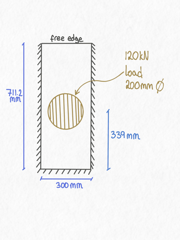
Plate_m2etpg.png
.

I'm trying to figure out how to analyse this.

This passes fine if analysed as a simply supported beam spanning in the short direction. Although I'm not sure if that is unconservative?

I looked in to Roark's stress tables but the only suitable case appears to be this one, which is conservative as it's simply supported instead of fixed (which is fine). However, it only considers a UDL load acting on the entire plate as shown below :

Roark_Table_-_Copy_epbe94.png


Is there a way that I can convert the concentrated load into a UDL acting on the entire plate.

My first attempt was to take the 120kN load and apply that over the area of the circle which has a diameter of 200mm. However, this resulted in a pressure of 3.82 MPa (120,000/31415.93), which doesn't work and seems a bit too conservative.

Can I take the point load and spread it over the plate area so : 120000/(711*300) = 0.57 MPa? Or will this concentrated load case not work with the Roark tables?

If not, would the initial approach designing as a simply supported beam spanning in the short direction be a reasonable approach? Designing as a beam that is 3/4" deep and 300mm wide with a 120kN point load in the center. The ratio of plate lengths is 711.2/300 = 2.37
 
Replies continue below

Recommended for you

Redacted said:
This passes fine if analysed as a simply supported beam spanning in the short direction. Although I'm not sure if that is unconservative?

By "passes fine if analysed as a simply supported beam" I assume you're saying no limit state is overstressed. If that's the case, and the limit states are ductile, then the analysis is guaranteed to be conservative by the Lower Bound Theorem described in the AISC Design Guide 29 Section 1.2.

Yield line analysis would be pretty easy for this plate also.

Edit:

The text above is about computing the ultimate strength of the plate. If you're limited to some elastic stress, then what I typed doesn't help.

If deflections are important you'll also need to come up with another method. Any FEA program that includes shells or plates should make quick work of this problem.
 
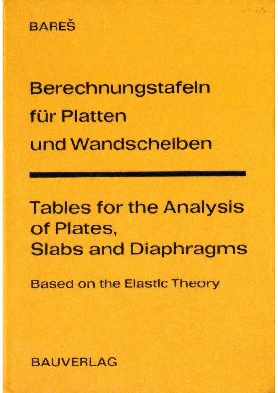
I found on web this manual (I downloaded free) : there are a lot of cases and loads. Tomorrow I will look better which one is suitable fo you

Bares_en_JPG_txejq2.jpg
 
I would guess that given the relatively large load and low bending stiffness of a 19mm plate the structural behaviour would be more like a cable and the stress would come from membrane forces due to deflection (assuming supports cannot move).

 
How is the load applied; is the object fairly rigid? to be considered as a couple of point loads near the circumference and how is it attached? Is it rigid so the plate attachment can be considered fixed?

-----*****-----
So strange to see the singularity approaching while the entire planet is rapidly turning into a hellscape. -John Coates

-Dik
 
How I'd approach it- treat as a simply supported beam spanning the short direction, but assume a limited width of it (say, 300mm) was effective.
If it's a one-off item, you very quickly reach the point where it's cheaper to add extra plate than to spend more time analyzing.
The problem as shown would be a really simple finite element problem.
The issue mentioned above, about how you know how the force is actually distributed on the plate, would have a significant effect on the results.
 
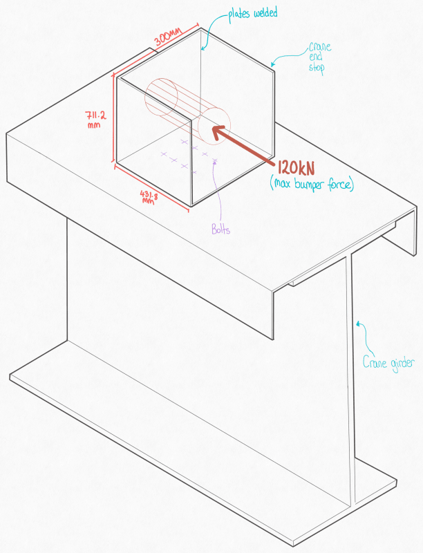
Thanks, everyone; for clarity, I added an isometric sketch. My original question was to do with the back plate that takes the impact load. See below :

Drawing_2_-_Copy_vcvc8s.png


The design is for a crane end stop. Only four will be fabricated, so I wouldn't mind a quick conservative calculation.

@271828 Yes, my design approach assumed a point load acting on a 300 mm-long beam.

Max Moment = PL/4 = 120*0.3/4 = 9kNm

M = σ * Z

Where z = bd^2/6

Thickness required = √((6*M)/(b*σ))

= √((6*9*10^6)/(711.2*250))

= 15.6 < 19 (3/4" plate)

@Dik the object is a crane bumper, not sure if the bumper material is rubber or steel.

@JStephen, thanks; I do have SAP2000, but I am not too experienced with FEA modelling. But I'll look into it if required. Any context for limiting the width to 300mm?
 
Add stiffeners (triangular brackets) behind the "bumper stop". That will transfer load in the plane of the stiffener directly into the crane girder web - i.e., the stresses will be small and stiffness will be large. It is not sensible to transfer large forces by cantilever action.

I also suggest welding the plates and stiffener to the girder (the configuration of bolts, as shown, is not particularly effective, and serves no purpose if you weld the plates), and adding web stiffeners at the location of the back plate.

Suggestions for limiting effective width of the flange are related to shear lag, but if you transfer forces as I described, you don't need to worry about bending action.

 
I would not expect this to be fixed. Maybe I'm wrong, but to me it does not "feel" fixed.
I also would not consider 711,2 mm to be an effective width, but a much smaller width - closer to 250 mm (200 mm of load width + plate thickness on each side).
I agree about the stiffeners, as cent mentioned.
 
How do you know what the maximum bumper force will be? Stops need to absorb the kinetic energy of the moving item; does the bumper have shock absorbers that will limit the load to 120 kN?
 
why not just bolt a piece of a WT section to the top of the crane beam and weld a thick plate to the bumper side. that's a pretty typical crane stop detail.
 
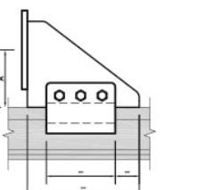
@centondollar, the sketch above is a bit misleading; there will not be much space behind the back plate for stiffeners. Originally there were typical end stops installed, something like this :

Crane_stop_typ_-_Copy_sq4atj.png


The original end stops were bolted into the girder.

The client wants to remove the original end stops and install a pocket system end stop. They would like to install the steel pocket end stop at the back of the girder to gain extra space required for maintenance purposes.

@3DDave, the max bumper force was provided in the crane drawings. It is 64kN at 100% speed. When factoring in a typical live load factor of 1.5, it is 96kN, and the client requested an additional 1.25 factor, which is 120kN.

@Dold Yes, that would be the easiest approach but the issue is the space constraint and maximising the space gain.
 
I do not understand the need to save a few hundred millimeters. Is there space behind the beam? That would allow for an end plate, vertical backing plate and stiffeners to be placed such that the crane movement is not restricted.

If there is no space behind the girder, you could place web bearing stiffeners at the end of the crane girder (a thick end plate would suffice), weld the vertical back plate close to the flange edge, and weld two or three stiffeners (extending say, 150 mm from the plate) connecting flange and vertical back plate.
 
I wouldn't look at this as having fixed edges on any side of the plate. I don't think the 431.8mm plates will be enough to give significant moment resistance at the edges, but I could be wrong. Also, with a plate of this ratio of side lengths, the boundary conditions on the short edges aren't as important, since they don't really affect what's happening at the center of the plate all that much. If you look at cases 1b and 2 from table 11.4 of Roark's (7th ed), the coefficients for both cases tend toward an asymptote as a/b grows (that's why you can't count on the full 711.2 mm to contribute).

If you use the simplifying assumption that the short edge boundary conditions aren't important and the edges are simply supported, then you should be able to use cases 1b and 1c from Roark's, which both give similar results.
 
Status
Not open for further replies.

Part and Inventory Search

Sponsor