Continue to Site

Eng-Tips is the largest engineering community on the Internet

Intelligent Work Forums for Engineering Professionals

  • Congratulations waross on being selected by the Eng-Tips community for having the most helpful posts in the forums last week. Way to Go!

Steel Angle Bending/Splitting 1

Status
Not open for further replies.

ryaneng

Structural
Mar 23, 2022
42
Hi all,

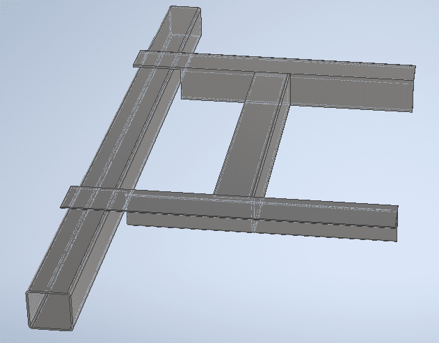
I'm reviewing some drawings from a steel manufacturer for some steel framing around a roof opening in a metal deck roof. The metal frame will rest on OWSJ's, and support the roof deck around the opening. What they've submitted doesn't match our details, but I do think it's a much easier construction, and could work in some situations. Our detail: Their drawing:
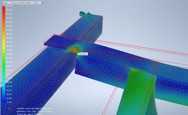
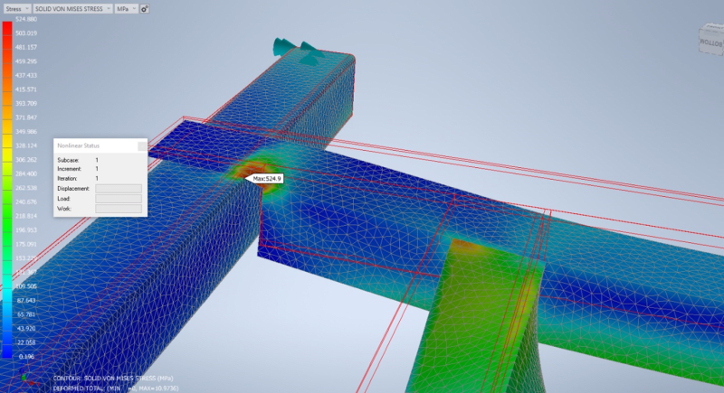
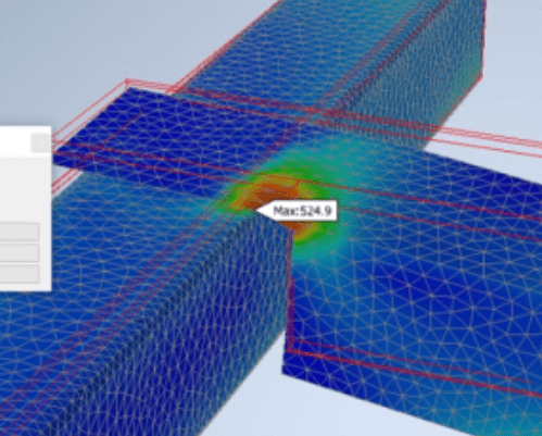
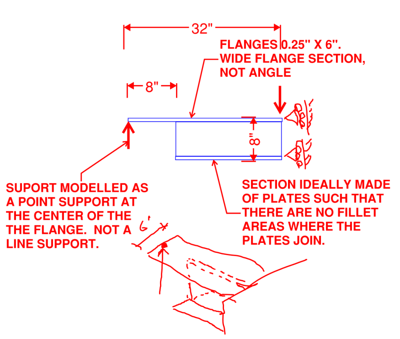
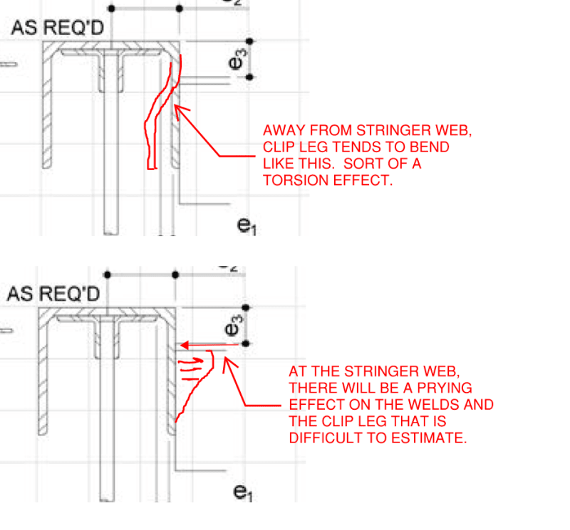
My main concern is the point where the flat steel angle portion meets the vertical web of the angle. The flat plate has enough bending capacity without the vertical, but what resistance does the member have to splitting where they join together. I think an easy fix is to simply add in a gusset plate where the vertical starts (or revert completely to our detail), but I think their detail is nice for constructability and I would like to use it in certain low load applications if I can prove it works.

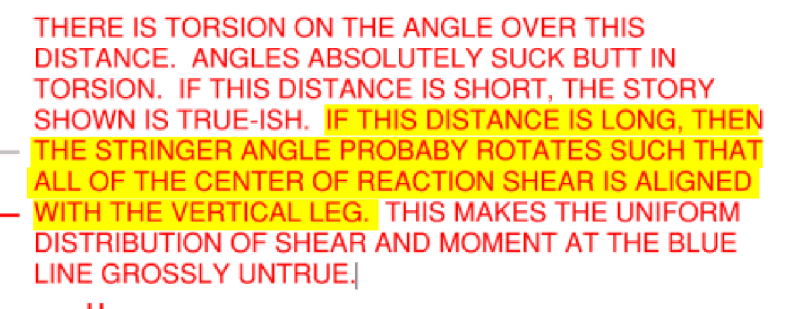
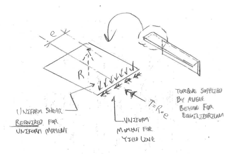
What are your thoughts? Am I missing something, or is there a straightforward check I can complete? Typically when members like this are coped the shear resisting vertical web is what remains...
 
Replies continue below

Recommended for you

Enable said:
...or do we think that weld just DOES NOT get done in a lot of cases (and angles just hang there) and that's why the roofers are saying they never cut open the deck?

That's my suspicion when the clip angle setup is used.
 
dik said:
I then calculate the moment based on the eccentricity of the support condition to determine the moment in the 'clip angle' at the end.

Firstly, the detail that you've shown is not the alternate one that OP's been asking about.

Secondly, the calculation method that you've described glosses over some important stuff in my opinion. See the sketches below. Just running the numbers of flat plate flexure of the clip strikes me as pretty optimistic.

C01_qlxyte.png
 
OP said:
I can calc the moment in the flat plate based on the UDL and check it works for bending as a plate, I'm more interested in how it behaves (and what I can count on) when the vertical leg is reintroduced.

In my opinion, this is the fundamental difference between the two setups. The view is from the top.

C01_pbkxtg.png
 
For retrofit jobs, we don't necessarily weld the angle clips to the joists. We make them put the angle clips in place, and then field cut the angle to fit tight between the clips. weld the angle to the clips. if fastening of the clips to the joists is necessary for uplift requirements, we may look at changing the detail to more easily allow connections. I, like Koot, am not a huge fan of just coping the vertical leg off the angle. the unzipping/splitting failure is what concerns me as well.
 
KootK said:
Do you assemble the frame in the field, angle by angle? Do you attempt to slot the coped, horizontal angle leg into the deck flutes or just lift the deck locally and put it wherever it needs to be? With a single piece angle, I feel like you'd need to come into a flute skewed at one end and then swing the other end into place, lifting the deck as you go.

Never done it myself. What you are saying is likely how things go down.
I wonder how many of these actually get welded.
 
I just let it yield... a tad. I'm more concerned about the force on the OWSJ if that's the support. If the loads were major, I'd design different connections.

Rather than think climate change and the corona virus as science, think of it as the wrath of God. Do you feel any better?

-Dik
 

It's illustrative only... I don't know how the contractor will pry up the deck locally (the deck should be cut at the opening), or slip it into a flute if the supporting angle is short enough. Unless there is movement, the connection is independent of the weld to the OWSJ, or however they secure it... not my circus, not my monkeys... the connection works and they seem to build it.

I just revised the detail, the attachment weld at the top will be a teks without calling it up.


Rather than think climate change and the corona virus as science, think of it as the wrath of God. Do you feel any better?

-Dik
 

I've already explained to the OP that for light loads, there is no problem with the proposed connection. My detail does not accommodate the proposed condition. I don't use the single clipped leg for anything other than picking up deck for a roof perforation... I don't use it for real loads, but you can design for it, if you have to. If you clip the leg from an L8x8x0.5, then you can pick up some 'heavier loads', but you can design for it. No rocket science.

Regarding your marked up comments. I treat the reaction from the flexural angle at the face lf the clip angle... as pure shear; I don't consider a moment. The clip angle is flexible enough that any moment resistance would be small. I then add the thickness of the clip angle to the e1 dimension to get the eccentricity of the moment in the clip angle. I compare the factored moment to the resisting moment. Again, no rocket science.

You've confused me regarding the supporting conditions. The reaction on the clip angle might be near the centroid of the length and the shear centre of the flexural angle might be near the mid thickness of the vertical leg. Moment is relatively small. I don't know where you are getting your assumed centre of reaction from... it's nothing like that. Any 'tipping' would cause the centre of reaction to move closer to the shear centre. I'm not concerned about minor variations... If I have a major load, then I address it... for smaller loads... I sleep sound. Again, no rocket science.

As far as welding the clip angle to the OWSJ, I've modified the SMath sheet to show a Teks, but have left the calcs alone (It defaults to a pinned connection). I've left the weld calculations in place in case I need to develop moment (assuming whatever is supporting the clip can take it.) I still check the weld if applied for half the moment assuming it fixed, in case I need it. The program defaults to a pinned connection, anyway.

Rather than think climate change and the corona virus as science, think of it as the wrath of God. Do you feel any better?

-Dik
 
dik said:
I don't use it for real loads, but you can design for it, if you have to. If you clip the leg from an L8x8x0.5, then you can pick up some 'heavier loads', but you can design for it. No rocket science.

Torsion in an angle is about as close as we get to "rocket science" in steel member design. Design Guide 09??

dik said:
Regarding your marked up comments. I treat the reaction from the flexural angle at the face lf the clip angle... as pure shear; I don't consider a moment....I then add the thickness of the clip angle to the e1 dimension to get the eccentricity of the moment in the clip angle. I compare the factored moment to the resisting moment. Again, no rocket science.

No matter how you slice it, there is moment being transferred from the vertical face of the clip angle to the end of the flexural angle. It's the beam reaction times the distance from the centroid of that reaction to the connection interface.

dik said:
The clip angle is flexible enough that any moment resistance would be small.

The clip angle's flexibility is irrelevant as it is the only path available for moment resistance as a matter of equilibrium. The stiffness of the angle only affects the degree to which the prying issue is amplified.

dik said:
I don't know where you are getting your assumed centre of reaction from... it's nothing like that.

The center of the shear reaction at the support is perfectly reasonable where I've shown it assuming a short length of the flexural angle in torsion and a stiff, rectifying cross member as I described previously. Moreover, it's the location that is consistent with the flexural yield line that you propose checking for the design.

dik said:
Any 'tipping' would cause the centre of reaction to move closer to the shear centre.

That's just what I meant by in the highlighted statement below. The center of reaction will be somewhere between the location that I showed in my sketch and the shear center of the flexural angle depending on how stiff the torsion path is within the system.

c01_v4htcq.png
 
Quote (dik)
I don't use it for real loads, but you can design for it, if you have to. If you clip the leg from an L8x8x0.5, then you can pick up some 'heavier loads', but you can design for it. No rocket science.

Torsion in an angle is about as close as we get to "rocket science" in steel member design. Design Guide 09??


Torsion is complicated, but you don't have a lot of it here! I think you are looking for problems that aren't there.

Quote (dik)
Regarding your marked up comments. I treat the reaction from the flexural angle at the face lf the clip angle... as pure shear; I don't consider a moment....I then add the thickness of the clip angle to the e1 dimension to get the eccentricity of the moment in the clip angle. I compare the factored moment to the resisting moment. Again, no rocket science.

No matter how you slice it, there is moment being transferred from the vertical face of the clip angle to the end of the flexural angle. It's the beam reaction times the distance from the centroid of that reaction to the connection interface..


You are still only transferring the moment caused by the reaction times the thickness of the clip angle leg + e1 (I generally set e1 as 1" max, for fitup), and this moment is taken by length of the clip angle. The stiffness and strength of the thickness of the clip angle leg pales in comparison to the stiffness and strength of the flexural angle. To be conservative, I don't reduce the moment in the flexural angle by this small end moment. [pipe]

Quote (dik)
The clip angle is flexible enough that any moment resistance would be small.

The clip angle's flexibility is irrelevant as it is the only path available for moment resistance as a matter of equilibrium. The stiffness of the angle only affects the degree to which the prying issue is amplified.


The clip angle's flexibility is what allows you to treat it as fixed at the flexural angle and use an eccentricity of the angle thickness + e1.

Quote (dik)
I don't know where you are getting your assumed centre of reaction from... it's nothing like that.

The load on the flexural angle is approx the shear centre of the angle or maybe near the centroid. The 'reaction' on the clip angle is approximately have the length of the clip angle. The distance is small.

The center of the shear reaction at the support is perfectly reasonable where I've shown it assuming a short length of the flexural angle in torsion and a stiff, rectifying cross member as I described previously. Moreover, it's the location that is consistent with the flexural yield line that you propose checking for the design.


Unless we're talking about different things, the reaction on the clip angle would be in the middle, and not at the end as you have shown. With any deformation this would move towards the shear centre or centroid of the flexural angle. Any torsion generated is negligible, IMHO.

Quote (dik)
Any 'tipping' would cause the centre of reaction to move closer to the shear centre.

That's just what I meant by in the highlighted statement below. The center of reaction will be somewhere between the location that I showed in my sketch and the shear center of the flexural angle depending on how stiff the torsion path is within the system.


... and much closer to the shear centre, but definitely between the mid point of the clip angle and the shear centre. I think it's time to drop this. [pipe]

Rather than think climate change and the corona virus as science, think of it as the wrath of God. Do you feel any better?

-Dik
 
dik said:
Torsion is complicated, but you don't have a lot of it here! I think you are looking for problems that aren't there.

And I think that you are entirely ignoring one of the most important aspects of the design of these systems.

dik said:
The stiffness and strength of the thickness of the clip angle leg pales in comparison to the stiffness and strength of the flexural angle. To be conservative, I don't reduce the moment in the flexural angle by this small end moment.

The issue is not the moment in the flexural angle but, rather, the moment in the connection between the clip angle and flexural angle. And the relative stiffness between the clip angle and the flexural angle does not affect the load distribution within the connection at all. This is because the connection is made to the web of the flexural angle which is, for the purpose of the connection design, effectively rigid.

dik said:
Unless we're talking about different things, the reaction on the clip angle would be in the middle, and not at the end as you have shown.

How about a sketch? Heck, take mine just add a dot and an arrow to it or something.

dik said:
Any torsion generated is negligible, IMHO.

And in my opinion, it's the dominant design issue for the alternate scheme proposed by OP's fabricator. Moreover, since you're obviously not checking the torsion, it would seem that your opinion in this is based on qualitative judgement at best.

dik said:
I think it's time to drop this.

Then drop it. You can't expect to terminate the conversation and have the last word all in one post.
 
Sure I can... SMath programs attached.

[URL unfurl="true"]https://res.cloudinary.com/engineering-com/image/upload/v1649892741/tips/Steel-Equip_Support_L_jickbr.pdf[/url]

[URL unfurl="true"]https://res.cloudinary.com/engineering-com/raw/upload/v1649892742/tips/Steel-Equip_Support_L_mfi8if.sm[/url]

Rather than think climate change and the corona virus as science, think of it as the wrath of God. Do you feel any better?

-Dik
 
I prepared the sketch below to further explain my belief that there is no way to do these two things simultaneously:

1) Utilize a weak axis, flexural yield line that is the full width of the horizontal angle leg and;

2) Reduce or eliminate the torsion in the stringer angle.

Fundamentally, I believe that this is because, once a full width uniform flexural yield line is chosen by the designer, a commensurate full width shear field is necessary on that line in order to satisfy equilibrium. So the only path to reduced angle torsion, then, is to assume a flexural yield line width shorter than the full angle width.

C01_fl4guh.png
 
Jeez guys! It is just a small roof support! Go have a beer! [upsidedown] (Though even the smallest design challenges can have deep engineering/learning.)

Well I have had a couple beers now and because I was politely asked to stick my head in here, I have done so and had a read. This whole approach for roof penetrations is unfamiliar for me so it has taken a fair bit of brain power just to get my head around what is happening. Not to mention the different terminology and roof framing approaches. Oh and to add to all that you guys are much more adept at using appropriate engineering terminology, I just try go with my gut and then try to manipulate the mathematics or the computer to align with my gut [rednose].

Kootk dragged me in here to have a look at his sketch above, so I have done so. To me it makes sense, as did his previous comment on this matter. There is no way the full width of the horizontal angle leg can be engaged. (I'm sure this can be adequately demonstrated with FEA which I am known to lean heavily on, but I don't think it is necessary here.)

In my mind I'd treat the connection to the OWSJ as a bearing connection as though the weld isn't even present. In which case the angle would rotate until it bears mostly about the "R" shown in Kootk's drawing. If weld IS present the the result is mostly the same just with more torsion in the angle and an greater reaction at "R" and tension at the toe of the angle.


Going back to the start. I agree there is plenty of reasons not to like the alternative approach. I don't agree that the original approach is more difficult/expensive to fabricate but it is more difficult to retrofit as exhibited by the good drawings from XR250.
 
human909 said:
Kootk dragged me in here to have a look at his sketch above, so I have done so.

The intent of my summons was not to get your input on our little deck angle discussion although your comments are, of course, welcome. I believe that I'm on to something much deeper than that which, I hope, might answer a long standing question that I have regarding concrete flat plate design.

If you consider the sketch below in the context of this thread, you'll agree that we have two, competing wishes for this:

1) We would like to be able to use the full width of the flange in flexure, ala yield line voodoo.

2) We would like the center of shear in the cross section to stay close to the shear center of the cross section in order to limit torsion on the member.

I hypothesize that those two wishes are incompatible. I believe that, once you lay claim to the full flange width in bending, that locks you into spreading the shear out uniformly as well. And I believe that I can prove this, somewhat, via hand sketched physical reasoning which is, as you, my preference with most things.

Ideally, what I would also like to do is model the setup in a way that would confirm or refute my hypothesis. However, the model would have to incorporate flexural plastification along the bend line and the associated redistribution of internal forces. Is this something that you would have the ability to do if you had a mind to take it on?

Should you be feeling super keen, please don't run off and model the angle. I would want to test a similar, easier, more strategic setup.

C01_dwtsdd.png
 
I can crank the handle and run a model of your choosing. I can model the whole setup here without too much difficulty. But I cannot model "flexural plastification", I did have a quick check of Nastran InCAD which I use, but no plastic modelling that I can see. Scratch that I can deal with plastic deformation... Give me the idealised model you want and I'll run it. Honestly I think modelling the full angle setup is workable and not difficult.

Kootk said:
I hypothesize that those two wishes are incompatible. I believe that, once you lay claim to the full flange width in bending, that locks you into spreading the shear out uniformly as well. And I believe that I can prove this, somewhat, via hand sketched physical reasoning which is, as you, my preference with most things.
I agree they are soley incompatible for the reasons you stated.
 
I modelled it up.

The model (half model using symmetry)
1_cgcbfu.png


Without plastic deformation:
2_cjjqd6.png


With plastic deformation:
3_clcmhj.png


Nothing amazing or surprising to see here IMO. But if you want me to do more just ask.
 
human909 said:
I modelled it up.

Dude, what did I just say?

KootK said:
Should you be feeling super keen, please don't run off and model the angle. I would want to test a similar, easier, more strategic setup.

Kidding, obviously your at liberty to model whatever you want to model. That said, I have a very different model in mind that will be designed to strategically tease out the things that may be "amazing or surprising". That stuff tends to get lost in the noise of unnecessarily complex modelling exercises.

As far as what you've modelled so far goes:

1) If the plasticity has been modelled as we discussed, there would pretty much have to be an interesting result in there somewhere. Either the shear at the bend line is uniform or it is not. Either way, I for one would find the result interesting.

2) I feel that the interesting things to see from a reporting perspective will not be the Von Mises stresses but, rather, the principle bending and shear stresses at the plastified bend lines. If the plastification has been modelled as we wish, there really shouldn't be a flexural stress hot spot as shown below.

Again, though, I would recommend holding off for the more strategic modelling setup.

c01_lpok5y.png
 
This is what I want to model. I mean to make this exercise it's own thread but, since your patience wanes, I figured it best to get this in front of you sooner than later.

c01_zktaj3.png
 
Also, if there is some way to make the yield line bend line a boundary condition such that the plate elements butt up cleanly and squarely to it, that would be helpful.
 
Status
Not open for further replies.

Part and Inventory Search

Sponsor