Continue to Site

Eng-Tips is the largest engineering community on the Internet

Intelligent Work Forums for Engineering Professionals

  • Congratulations waross on being selected by the Eng-Tips community for having the most helpful posts in the forums last week. Way to Go!

Statics problem

Status
Not open for further replies.

Acing

Mechanical
Mar 4, 2016
8
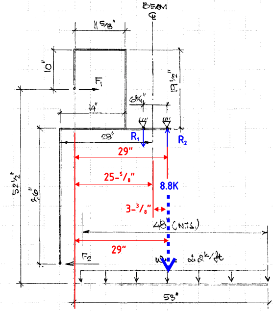
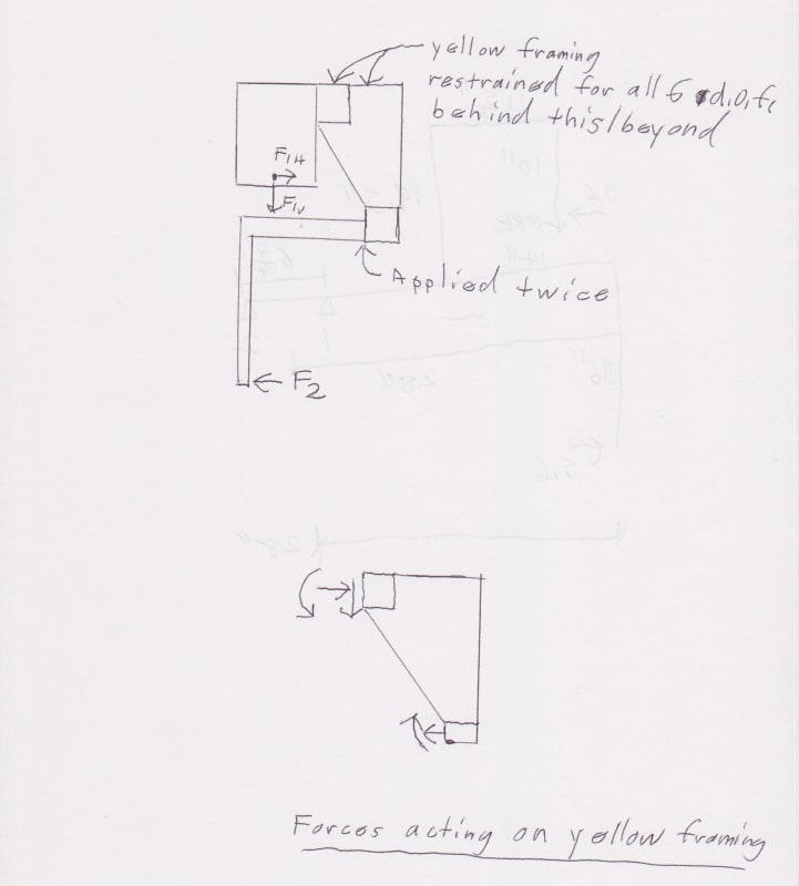
It is one of those brain freeze moments. I need some help with the statics for attached lifting beam fork analysis. Will the fork induce any torsion in the beam? It is supported at the bottom flange with wheels on ea side. How to resolve for forces in the setup. Thanks....
 
 https://files.engineering.com/getfile.aspx?folder=d9969127-7fe9-4eed-b89b-5d9d914706c2&file=20180413_131000.jpg
Replies continue below

Recommended for you

You need to take a stab at a FBD yourself (or give more info). I cannot tell what is what from that pic.
 
Is this an adaptation to a gantry trolley? If so, and the weight is directly under the center of the beam web, there is no net torque on the beam, but there may be internal bending and torsion loads in the trolley and the attachment.
 
I think we need more information to give advice
Can you make a sketch showing the system and the load path ?
 
My apologies as it wasn't very clear from the pic. I have attached schematics of the lifting device. The lifting device is supported on the bottom flange with wheels on ea side. I am trying to determine if the load will induce any lateral force in the beam bottom flange and if it does then how to cancel it out. I hope the attachment explains.
 
 https://files.engineering.com/getfile.aspx?folder=6a68d2f6-6cf3-474d-b75c-7d25ca4aa429&file=SilverStone_Beam-01.pdf
Ok, I think I get it now. Assuming the location of F1 is a pin (and it's missing the vertical reaction by the way).....yes, I can see how the moment caused by that load of the fork would be resolved into the couple of F1 & F2. Those reactions (i.e. F1 & F2) would kick some moment/torque into your "yellow" framing.

Your FBD doesn't quite match the pic (IMHO).
 
Thanks for the quick reply WARose. I just started resolving it when I posted the last diagram so that is why it is missing forces. I wanted to convey the idea of what I am after. What I have found it that F1 will be equal to F2 so these will cancel each other out. But the vertical reaction thru the pin will be carried into the frame and that will cause the torsion in the beam.
 
What I have found it that F1 will be equal to F2 so these will cancel each other out. But the vertical reaction thru the pin will be carried into the frame and that will cause the torsion in the beam.

Looking at that pic....I don't see how F1 & F2 could "cancel each other out" as far as that yellow frame is concerned: they've got different moment arms to generate the moments/torques that get dumped into the yellow framing.

[red]EDIT[/red]: By the way, just so I'm not missing something here: how does that whole thing get lifted off? Is the yellow framing attached to the truck somewhere?

 
Yes, the yellow bar is attached to a forklift truck. Regarding F1 and F2, net Fx (horizontal) should be zero this means F1 = F2 with opposite sign. Similarly I am proceeding with net Fy = 0 (vertical) to find out support reactions.
 
If I understand the situation correctly:

Applied load = 2.2*53/12 = 9.7k
Eccentricity from beam centerline e = 28 - 53/2 = 1.5"
Center of load occurs at 1.875" from one reaction or 4.875 from the other.

R1 = 9.7*4.875/6.75 = 7.0k; R2 = 2.7k

Torsional load to beam = 9.7*1.5 = 14.55"k

I don't know what you mean when you talk about panel width of 48" which means that I may have misinterpreted the problem.


BA
 
Okay, I think I get it now. If the 48" panel weighs 8.5k and aligns with the end of the fork, then centroid is 53 - 24 = 29" from the mast which is an eccentricity of 1" from beam centerline. This means R1 and R2 are 4.375" and 2.375" respectively from the beam centerline.

So R1 = 2.375*8.5/6.75 = 2.99k; R2 = 5.51k

Torsional moment = 8.5"k

BA
 
[blue](Acing)[/blue]

Regarding F1 and F2, net Fx (horizontal) should be zero this means F1 = F2 with opposite sign. Similarly I am proceeding with net Fy = 0 (vertical) to find out support reactions.

I agree that F1 & F2 are equal. However the reactions they generate should be different based on that geometry. (The vertical reaction at the pin will also have a effect.)

I may do a FBD of my own tomorrow to reflect what I think is happening.
 
It is not necessary to calculate F1 and F2 in order to determine the reactions at the beam. The torsional moment on the beam is P*e where P is the applied load and e is the eccentricity.

BA
 
[blue](BAretired)[/blue]

It is not necessary to calculate F1 and F2 in order to determine the reactions at the beam. The torsional moment on the beam is P*e where P is the applied load and e is the eccentricity.

I don't see how that is possible. F1 & F2 have different moment arms (either to the center line of the yellow beam or to the face of it).
 
F1 and F2 are not applied forces. They are intermediate resultant forces. They are equal and opposite and are separated by a distance of 36 + 9.5 = 45.5" vertically. To be consistent, there should be two additional intermediate vertical forces, Fvert separated by 14 - 11.625 = 2.375" horizontally.

The "F" forces taken together are equivalent to a moment acting on the system. Differences in moment arms of individual forces about a particular point is not relevant. The forces can be calculated but it really is not necessary if the only object is to determine reactions at the two support points.


BA
 
If I understand this right - the I-Beam is attached to the fork truck and this carriage is intended to provide a variable width lift. The lower portion is allowed to pivot at F1 from the upper attachment to the trolley portion and has a rotation stop at F2.

In that case, F1 and F2 need to be calculated but they are internal to the arrangement relative to the I-Beam since the lower portion loads are equal and opposite to the loads applied to the trolley. Since they are internal, they have no effect on the reaction at the I-Beam.

Sum all the moments of the applied loads and any considerable gravity loads about R1 and divide by the distance to R2 to get the reaction at R2. Do the reverse to get the reaction at R1.

The torque they apply to the beam will be as BA suggested Weight times the horizontal distance from the center of the beam.
 
Using the same method as BA, and IF my measurements calcs are correct, the vertical line of action of the applied equivalent load passes through R2:

Capturestatics_ywxs00.png


Which is the same result as Acing (calculating F1 and F2 first) with a R1 = 0 and R2 of 8.8k, except for a bit of rounding on your behalf.
 
so what are F1 and F2 doing ?

and how does the load attach to the frame and reaction points ?

another day in paradise, or is paradise one day closer ?
 
[blue](Acing)[/blue]

Hi BA....I am reaching at a different conclusion. Please see attached calcs. I appreciate your input in this matter.

Using your FBD, I came out with identical numbers. (And the magnitude of F1 & F2 are greatly reducing the reactions at the supports.)

However, I still do not (100%) agree with your FBD. From looking at your pic in the OP, to me, the application would look more like this:

4.18.18_001_er8rnd.jpg


I don't have the dimensions to solve and give the resultant torque....but hopefully you get my drift. F1h & F1v are at the location of that pin the fork hangs off of.
 
Status
Not open for further replies.

Part and Inventory Search

Sponsor