Continue to Site

Eng-Tips is the largest engineering community on the Internet

Intelligent Work Forums for Engineering Professionals

  • Congratulations cowski on being selected by the Eng-Tips community for having the most helpful posts in the forums last week. Way to Go!

Statics or FEA required? Frame Drawing in Post 5

Status
Not open for further replies.

P1ENG

Structural
Aug 25, 2010
237
I am trying to calculate the brace force of the attached frame. I can do it easily in RISA, but I want to incorporate it into a MathCAD calculation because it will be easier and faster to produce a calculation set for future projects. I've been racking my brain to figure it out because I know the stiffness of each element affects the load that the brace sees. So, I tried to simplify the properties of the members in the attached. The brace has the weakest moment of inertia and and cross-sectional area, I and A respectively. I then made the other members have arbitrary factors of I and A. The column is fixed to the foundation. The beam and braces have pinned ends. I showed the force outside the one column, but it is actually at the center of the beam (diaphragm load) so it loads each brace equally.

So am I stuck using RISA for each frame that comes up or can someone provide a (maybe not simple, but shortish) method of calculating by hand?
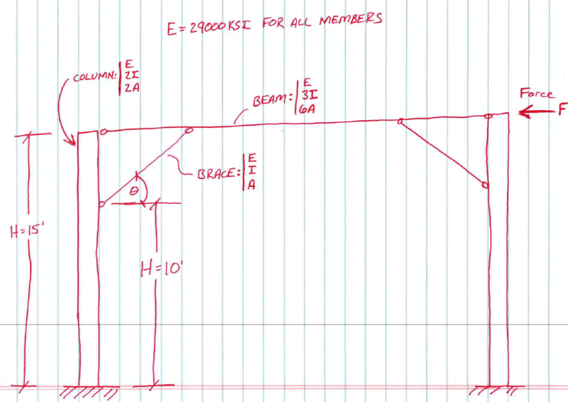
2_i6tdb8.png


On a related note, if the base of the column is pinned, I did an "equivalent" analysis of the column as a beam with pinned supports at the beam and brace and a point load (equal to 1/2 the force) at the foundation which is assumed the free end. This works with the assumption that the translation at the brace and beam are equal. This is not exactly true, but because of the stiffness of the members and close proximity of the two points, ends up pretty close. The pinned base requires a stiffer column to keep the drift down, hence my attempt at the above.

Juston Fluckey, SE, PE, AWS CWI
Engineering Consultant
 
Replies continue below

Recommended for you

XR250 said:
Time is money in this business.
I would know this being (successfully) self-employed. My situation is not yours and my goal is to save time in the long run. I appreciate a lot of people on this site, but a lot of times people want to understand the "why" of the question before answering or just make a completely different suggestion. I know what I want to do. If you can help me, great! I already know I could do it several different ways.

Juston Fluckey, SE, PE, AWS CWI
Engineering Consultant
 
OK. If you ignore the little crossbraces you can solve the 3 beam frame with fixed joints. The moment at each upper corner must be some very simple function of the ratio of the beam properties and the lengths of the beams.

Now in your actual structure that moment must be provided by axial forces in the cross brace and the two main beams, and moments in the main beams where the cross brace joins. That looks like structures 101 to me.

Cheers

Greg Locock


New here? Try reading these, they might help FAQ731-376
 
P1ENG,

Referring to your last comment - I greatly sympathize with your frustration of just wanting to stick to the problem at hand, rather than having to wade through a pointless sidebar conversation with those who try to explain how moot your post is. You are a PE and SE. There is little reason to treat you in that manner. It is a fair assumption to make that you do not need lessons in spending your work time wisely. 20 hours of my time a week is un-billed, which involves experimenting with projects similar to your post on real jobs I am working on. Sometimes the extra effort pays off, sometimes it doesn't. Frankly, I don't post much anymore because I am frequently concerned that I will be greeted with ad hominem attacks, or at a minimum, the vibe that others have been inconvenienced with task of reading, understanding, and answering the question(s).

-Mac
 
Check out the attachment. If it`s of any use to you, I`ve got a fully functional and well vetted MathCAD algorithm for doing general 2D FEM. My original dream was to turn it into my own version of RAMSBeam. I gave up back in 2010 and would pleased as punch if it could somehow be of value to another engineer. It looks like a lot but most of it is actually pre & post processing. The FEM itself is really just half a dozen subroutines. For your application, I`d probably just run it to get the moments required to reduce the problem to something determinate and then use your own tools from there.

I always thought that a nice feature in commercial software would be to be able to call it simply as a component from Excel. You know, feed it some nodes and loads table style and get some responses back in return. Stick FEM is pretty ancient tech. I feel as though we all just keep reinventing the same thing over and over again unnecessarily.

MacGrubber22 said:
Frankly, I don't post much anymore because I am frequently concerned that I will be greeted with ad hominem attacks, or at a minimum, the vibe that others have been inconvenienced with task of reading, understanding, and answering the question(s).

This is unacceptable. I've got too much invested in your development to not have regular access to you as a colleague. If this is not your preferred medium, please see if you can't get in touch with me by other means.

I like to debate structural engineering theory -- a lot. If I challenge you on something, know that I'm doing so because I respect your opinion enough to either change it or adopt it.
 
 http://files.engineering.com/getfile.aspx?folder=4a506e99-0bfc-4ffb-b7a8-11fa2b608492&file=Imitation.pdf
At the risk of adding little value to the topic at hand
@KootK and P1Eng:
Give python a look we've been developing some tools over the last couple months that can tie in nicely to excel and even generate some DXF files. With the opensource libraries matplotlib, scipy, and numpy we've been able to create some decent modules the most advanced fully functioning one being a theory of three moment continuous beam tool that does all possible live load patterns and outputs enveloped ASD and LRFD results to excel csv file and to scale CAD file showing the enveloped shears, moments, deflections, and reactions.

Back on topic:
I would personally start with the pinned column base condition, especially with your two bolt base connections, and create a tool for that which like others have mentioned makes the problem simpler. I do like your approach with the 1 kip equivalent model in RISA.
 
i think the problem is easy to set up in excel, with dimensions as inputs. Mathcad is an option.

I think this allows you to appreciate though the different dimensions work in the solution, and to quickly say "this particular design is conservatively covered by this earlier design". Maybe you can see a general rule about sizing the members ... should they be the same section ?

Sure there are canned solutions, but I like someone figuring things out from first principles rather than just running RISA or a "25yo 2D frame program".

@IDS, can you run with pinned supports ?

another day in paradise, or is paradise one day closer ?
 
KootK - in retrospect, I may be acting a bit hyperbolic. It has only been a few rare times I perceived comments as personal attacks; by no means a majority. The snarky or snooty comments which (purposefully or not) undermine the intent of posts occurs much more often. I think we are all guilty of the latter at some time or another; it is an engineer's nature (I think!). It is frustrating to see some of these comments get so many stars - I learned that lesson when I had stars taken away, probably because they perceived similarly by admins.

P1ENG - I apologize for hijacking your post. To get back on track, wouldn't the classical portal method (attached) be the most simple to implement?


-Mac
 
 http://files.engineering.com/getfile.aspx?folder=ae5b50bd-0acd-4c41-ac22-6603b7e04a59&file=Portal_Frames_-_RC_Hibbler.pdf
Sorry all! I didn't get mad and leave. I just finished the project, got sidetracked with another project, and forgot about my post. Thanks for those that kept the discussion going.

KootK/Mac,
Thanks for the attachments. I need to look at them yet, but I will! Mac, I think that is what I was looking for. I couldn't remember the name of the method. Like I said, I was limited to Singularity Functions in school for beam analysis, not portals. I need to understand this method. I think I looked at it shortly when I was studying for the SE exam, but I couldn't find a good tutorial.

Celt83,
Python/programming certainly appeals to me. I don't know if I would choose Engineering or CS if I had to go back to school. Matlab opened my eyes to the enjoyment of programming. Unfortunately, I'm not that great. I run Linux at home and I've written a few scripts, but actual, large programs would probably just go over my head.

rb1957,
I agree that is better to understand what is happening rather than just using a piece of software. The problem is that people like you and me aren't appreciated when we ask questions. I always felt like my senior thought I was just questioning his instructions, but I really just wanted to understand the "why".

Juston Fluckey, SE, PE, AWS CWI
Engineering Consultant
 
Status
Not open for further replies.

Part and Inventory Search

Sponsor