Tek-Tips is the largest IT community on the Internet today!

Members share and learn making Tek-Tips Forums the best source of peer-reviewed technical information on the Internet!

  • Congratulations JAE on being selected by the Eng-Tips community for having the most helpful posts in the forums last week. Way to Go!

Specifying Flatness of a Derived Median Plane -RFS 2

Status
Not open for further replies.

Kedu

Mechanical
Joined
May 9, 2017
Messages
193
Location
US
Parallelism between the surfaces shown in fig 5-8 / ASME Y14.5-2009 is controlled within:

a.) 0.11
b.) 0.08
c.) 0.02
d.) 0.04
e.) 0.15
f.) 0.07
g.) None of the above

Edit: maximum allowable parallelism between the two surfaces dimensioned with 16h11 (15.89 - 16.00)
 
I don't think your question is phrased correctly. Per ASME Y14.5 parallelism is not between two surfaces, it's between a surface/centerplane/axis, and a datum. If the bottom surface was considered datum feature A then the top surface could be out of parallel with datum A by up to 0.11mm.

John Acosta, GDTP Senior Level
Manufacturing Engineering Tech
 
powerhound said:
If the bottom surface was considered datum feature A then the top surface could be out of parallel with datum A by up to 0.11mm.

John,
Are you saying that the derived median plane flatness (DMPF) as shown within 0.4 has no influence over the requested parallelism?
In other words if DMPF wouldn't be shown, the parallelism will be controlled by the same value of 0.11. Am I correct?
 
I agree, I didn't know quite how to answer at first because of the way it was worded. Thank you powerhound for the clarification.

I went back and forth on this and I am going to present a counter-proposal of 0.08 - my reasoning is directly related to the 0.04 DMP flatness control. My first instinct was 0.11 as well, however because DMP flatness utilizes the UAME I don't think it will allow a shape with that much parallelism error.
 
This is more complicated than I initially thought. I thought you were just presenting a figure from the standard that matched something you were dealing with. I didn't know you meant to include the flatness issue. I thought you were just asking about parallelism.

That being said, I'm putting a hold on my response until I can think about this some more.

John Acosta, GDTP Senior Level
Manufacturing Engineering Tech
 
Since the maximum variation in distance between the two surfaces is 0.11 and that variation could be the result of a uniform taper where the flatness of the derived median plane is zero, then isn't the amount of parallelism also 0.11 under that case?

There are other cases where the flatness of the derived median plane does have an effect - if one side is perfectly flat and the other side has an arc to it, the amount of arc is limited to 0.08 (twice the flatness limit) but that is less than the first case.
 
3DDave,
I would say that the paralellism error of one face relative to the datum plane derived from the other face can be more than 0.11. In your example of uniform taper, the datum plane for parallelism tolerance will not be parallel to the center plane of the taper but will be coplanar with one of the faces of the taper. In my opinion, if one starts to contract two planes parallel to each other and to the datum plane about the opposite face of the taper to bring them two as close to each other as possible, the smallest possible distance between them will depend on the length of the part. The shortest the part, the more paralellism error can be.

What do you think?
 
I was hesitant to give an answer and I asked somewhat similar question on linkedin. Hmmm .....as usually I am now confused with different answers received.
 
pmarc - that is true. One end of the taper it will be 0.11 higher than the other and the flatness of the midplane does not affect that. The spacing would be reduced by the cosine of the slope, but that's a tiny factor.

I would like to see the related calculations - how this is supposed to affect strength, deflection, or make some functional difference in the installed system that can be tied to these factors and not be just an academic exercise.
 
I have to correct my statement that in case of uniform symmetrical taper (16.000 at one end, 15.890 at the other end) the actual parallelism error can be more more than size tolerance 0.11.

To fully see/understand it I had to model this in my CAD software. The maximum possible parallelism error I get for the uniformly tapered tab of length 50 is 0.109999933450053, which is less than 0.11.

When I open up the size limits to 15.500-16.000, the maximum possible parallelism error is 0.499993750117181, which is still less than the total size tolerance 0.5.

For 14.000-16.000 size limits, the maximum possible parallelism error is 1.99960011996001 - less than 2 in this case.

-----

I was also incorrect in my assessment of influence of the length of the 15.890-16.000 tab on the parallelism error. When I change the tab length from 50 to 100, the possible error changes from 0.109999933450053 to 0.109999983362497. So it increases (and not decreases, as I originally thought) by a very tiny factor, as 3DDave said.

When I change the tab length from 50 to 10, the possible parallelism error decreases from 0.109999933450053 to 0.109998336287745. Again, it is a very tiny difference.
 
3DDave said:
installed system that can be tied to these factors and not be just an academic exercise.

I suspect it is an academic exercise..... and I think it is based on a previous question asked on linkedin....Just my assumption.

pmarc,
I am uncertain (based on your relpay above) if you agree with Norm's opinion that DMPF will control the parallelism within the same tolerance of the two faces (if one surface is made datum feature and the other is controlled with parallelism to it).
In other words, if DMPF is shown within 0.04 and the size tolerance within 0.11 (exactly as currently shown in fig 5-8) then the parallelism between the two surfaces is already controlled within 0.04.
Again, I guess you would not agree with that assessment.

Could you, please, confirm (only if you would like).

And no I am not putting you between a rock and a hard plate.

I am trying to learn, if possible, from each and every excercise (academic or not), issue, problem presented on different forums to improve my knowledge. Thank you pmarc.
 
greenimi,

In the first place - and here I am repeating after John (powerhound) and chez311 - there is no such thing as parallelism of two surfaces. Instead, there is parallelism of a surface relative to the datum plane derived from another surface.

If we redefine the question accordingly, I would say the maximum possible parallelism error is 0.11.
 
To all,

This actually hits on a topic that has been a question in my mind for a little while, and I am hoping to get someones opinion on it as it directly affects how I think about this topic. I may be way off base here and there may be some basic errors in how I set up my examples, but I do do believe my geometry and the basic premise is sounds.

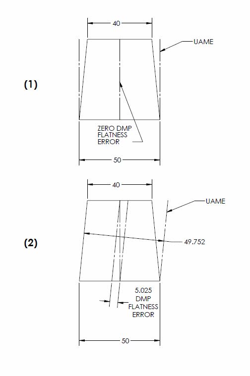
What do you guys think about the below figures? When a shape of "uniform symmetrical taper" is assessed in everyones above calculations, I believe you are assuming that the UAME looks something like #1 below which allows the parallelism error to be independent of any DMP flatness specification applied and only be a factor of the size tolerance (and therefore allowable taper). However, according to the definition of Actual Mating Envelope in Y14.5 section 1.3.25 "A similar perfect feature(s) counterpart of smallest size that can be contracted about an external feature(s) or largest size that can be expanded within an internal feature(s)" - which would be the UAME I have shown in example #2, as you can see it is the smallest shape which can be fit around the feature. A UAME defined as my example #2 means that even a part with "uniform symmetrical taper" will still have measurable flatness error.

Of course I have increased the dimensions to show my point more clearly, and I know that the size of the UAME will approach the size of the maximum dimension as the difference between the toleranced dimension becomes smaller however it seems that even this very slight difference in the way the UAME is defined has significant effects on how DMP flatness is measured.

Utilizing the sizes in Figure 5-8 referenced by Kedu the UAME (per my above definition of UAME defined by my example #2) of a shape of uniform symmetrical taper (16 at one side 15.89 at the other) is 15.99999032. This results in a maximum parallelism error that everyone has previously stated of ~0.11 (0.10999993 exact) however it results in a flatness error of ~0.055 (0.05500003 exact) which significantly violates the allowable flatness error of 0.04 - note my "exact" figures may differ from pmarc's due to slight rounding errors and how I set up my geometry. Note that the parallelism error is very nearly twice that allowed by DMP flatness, therefore if the UAME is to be defined in this manner I stand by my initial statement that the allowable parallelism is limited to 0.08


UAME_FOR_DMP_FLATNESS_wmrxtw.jpg
 
As an addendum there is a chance I was slightly off on my geometry and the flatness error shown in my exaggerated example #2 should be less than 5 (around 4.975) and my actual calculation based on the values from Fig. 5-8 should be less than 0.055 (0.05499997) - these would make more intuitive sense to me but I may still have slight errors in how I defined the Derived Median Plane so I will leave this as an addendum instead of editing the original post. All my other statements still stand.
 
chez311,

You are right, I assumed that for uniform symmetrical taper the UAME looks like on your picture (1). I agree that if we follow Y14.5 definitions, UAME should look like on your picture #2.

However... You assumed that the DMP flatness tolerance zone is parallel to the UAME. May I ask you why?
 
chez311, Isn't flatness a measure of the distance between parallel planes the median points must occupy with no mention of the UAME?
 
pmarc,
You are absolutely correct - I think I was stuck on the way the examples are presented in the text, even though its only flatness all the examples I looked at showed the tolerance zone what looks like approximately parallel to the UAME. Additionally the definition of Derived Median Plane mentions the UAME and taking segments normal to it which threw some more confusion in the mix. Thank you for knocking that one loose.

Thank you for answering my question about the UAME, that one has bothered me for a little while because I've even seen several examples from various places presented with it shown as #1.

3DDave,
The definition for Derived Median Plane involves drawing sections normal to the UAME and per the above, combined with the examples shown in the text, created some confusion in my mind and I got to thinking it had to be parallel. I lost sight of the definition of flatness, I realize my error now.
 
chez311 said:
The definition for Derived Median Plane involves drawing sections normal to the UAME

Is this true?
 
greenimi,

Straight from ASME Y14.5:

1.3.30 Derived Median Plane
derived median plane: an imperfect (abstract) plane
formed by the center points of all line segments bounded
by the feature. These line segments are normal (perpendicular)
to the center plane of the unrelated actual mating
envelope.

1.3.31 Derived Median Line
derived median line: an imperfect (abstract) line formed
by the center points of all cross sections of the feature.
These cross sections are normal (perpendicular) to the
axis of the unrelated actual mating envelope.
 
So after re-reading it, I didn't realize it at first but the distinction between "line segments" and "sections" is important in the definition of Derived Median Plane vs Derived Median Line - I apologize if it is misleading that I referred to "sections" in my replies, I hope that does not cause any confusion.
 
Status
Not open for further replies.

Part and Inventory Search

Sponsor

Back
Top