Continue to Site

Eng-Tips is the largest engineering community on the Internet

Intelligent Work Forums for Engineering Professionals

  • Congratulations waross on being selected by the Eng-Tips community for having the most helpful posts in the forums last week. Way to Go!

Slab on grade cast on compacted soil 4

Status
Not open for further replies.

fa2070

Structural
Jun 6, 2007
58
Hello,

Let's consider this situation.
I need to design a concrete slab-on-grade for a site with an ML-type soil. (sandy silt). The contractor is going to strip the upper layer of natural soil (1.00m thick) and replace it with sheepfoot-roller compacted structural fill (k > 300pci). The underlying strata are natural soil (-1.00m and beyond).
My question then is,
What modulus of subgrade reaction "k" do I have to use in my calculations to design this slab-on-grade? Should I use the "k" of the underlying natural silt or the "k" of the roller compacted fill (which ultimately will be supporting the slab) ?

Thanks.
 
Replies continue below

Recommended for you

I'll take a stab at this, but bear in mind that ACI is considering some guidance on this (not that I agree with their suggested guidance).

I'd recommend the subgrade modulus of the subbase (i.e., 300 pci). That said, you still may have problems.

Here's what's at issue: The subgrade modulus is used as a structrual engineering contrivance to model deflections and failures from modeled point loads. (I'm sure you know this aready) - It is a series of "springs" that are considered to act on the underside of the slab. So in effect the soils in proximity to the underside of the slab are what represent the "spring".

Here's where the body is buried: What if you have a properly designed slab (i.e., structural integrity for these concentrated loads) but the entire system is sitting on a natural soil (let's say 5 ft below the slab) that is soft and compressible? Well, this soft zone may have no affect on the slab design but may have a HUGE affect on the slab performance. In other words the structure may tolerate a point load and transfer the deflection to the adjoining "spring" (i.e., new subbase) just fine, but the ENTIRE slab AND subbase under uniform loading may settle/crack.

ACI has received a draft guidance suggesting the use of a "long-term" k value (a reduction value) to address this concern. I think this is the wrong approach.

I would propose that you do a settlement/compression analysis for the design areal load and consider the likely extent of settlement of the ML to be realized by the design load. If the settlement is too great, who cares what value of subgrade modulus you use. Whether you use 50 or 500, the slab may not perform very well.

Then again, maybe you have some additional project details that may change my ranting.

f-d

¡papá gordo ain’t no madre flaca!
 
300pci seems high (but that's in reference to my part of the world where we have lots of ml and sm except that we have a lot of mica included--cbr's from 3-7 are very common). however, assuming that the underlying conditions are not suspect for large settlement and you're scenario is just like you state, i would use the material that is recompacted. there are things that you can do to help you pci...for example, using base course material/graded aggregate base or even a cement/lime modified soil will help that number out. and obviously having a higher degree of compaction will also help.
but ultimately, just as fattdad indicates, you've got to consider the "bigger picture" as well.
 
fattdad's right.

You've got to look at it in two ways; consider subgrade moduli for the site when thinking about the stability directly under the slab (from spring to spring), and then the overall settlement (which the subgrade moduli do not address).

When someone tells me they've just added 3 feet of imported, well compacted fill to a soft soil site, and then they want me to tell them the "subgrade modulus" for a mat foundation, I sort of feel like a robot; "Syntex Error-Does not compute."

First make sure your soils down deeper aren't prone to settlement under your site conditions, then, if your subgrade directly below the slab is proofrolled and uniform in density, then you can get any with using a normal k value for design (say 200pci to 300pci or whatever is appropriate for your silty soils). If there are any concentrated loads, you'll need to vary your k since it is not constant. And speaking of silty soils-is frost a concern where you're at?
 
Thanks to all who responded.
Just, by chance fattdad, do you know what ACI committee is preparing the draft?

The following case is not related to my original post, although both share some similarities.

fattdad said:
Here's where the body is buried: What if you have a properly designed slab (i.e., structural integrity for these concentrated loads) but the entire system is sitting on a natural soil (let's say 5 ft below the slab) that is soft and compressible? Well, this soft zone may have no affect on the slab design but may have a HUGE affect on the slab performance. In other words the structure may tolerate a point load and transfer the deflection to the adjoining "spring" (i.e., new subbase) just fine, but the ENTIRE slab AND subbase under uniform loading may settle/crack.

What you say resonates with something that happened to the floor of a circular wastewater storage tank that we built last year, although I didn't participate in this project personally. It is worth highlighting that the client purchased a "standard" tank. They didn't request a custom design and thus no calculations or soil probing were carried out. On the other hand, the only prerequisite that our sales department demanded was that the soil had to have a bearing capacity 1kg/cm2. So, the client on his own decided to strip the upper meter of natural soil and replace it with compacted structural fill. And then we built the tank (diameter=20m, height=4.5m) with its monolithic, jointless concrete floor (thickness=12cm), as has been common practice for decades.

Fast forward to today and the client is claiming that the floor is fully cracked and that due to unacceptable leakage the tank is now out of service. A visual inspection reveals that the floor is, with no doubts, severely cracked. A few major (e.g. 4mm wide) circumferential, concentric cracks and a number of radial, narrower ones. Surprisingly, the wall remains mostly intact save for a few, almost negligible cracks. As can be inferred from the rainwater on the photos, either the perimeter settled or the center suffered upheaval. A forensic inspection carried out by a third party suggests that the latter is what ultimately happened. Had the perimeter settled -so they say- the walls would have suffered significant damage (neither of these assertions can be 100% confirmed though). What type of soil is there at the site ? Well, according to a report from last week there are 5m of CH (impervious expansive clays, allowable stress=0.45Kg/cm2) underneath the 1m-thick structural fill, and then 3m of ML (clayey silt, allowable stress=2.3Kg/cm2) underneath the expansive clays. Water table at -0.45m, frost not a concern. Had we known this one year ago! Now, we're still in the middle of a "negotiation" to establish whose responsibility this failure is before setting up a repair schedule. The client is fully aware that a fair share of the responsibility is theirs for having overlooked the presence of clays.

Anyway, in the coming months we'll be building two more tanks almost side by side with this one. It is clear that a 1m-thick, sheepfoot roller compacted structural fill + a 12cm concrete floor aren't enough.

My questions then are, how do I go about designing a floor for these new tanks?
Will a ribbed floor suffice or will I have to use piles?
Carry out a settlement/compression analysis as fattdad suggests?
How about soil cement?

It's been stated that it's the big picture that matters. That's perfectly clear, but I've got to start somewhere with the design of the floor.

Thanks.

pic1.jpg


pic2.jpg
 
Mike Duncan (Virginia Tech) has a great publication on this EXACT topic and has normalized graphs that depict various settlement profiles. I'm on vacation next week but if you send me an email I can reply when I return with a proper citation. cbenson AT mckinney-usa DOT com

If you take the dead load of the tank, you will quickly realize that the wall/roof loads of the tank dim in comparison to the live load. For a tank with a 60 ft diameter and a 20 ft height, you have a large areal load (from a water-type fluid) on the order of 1,300 psf. Heck, that's nothing for bearing capacity (i.e., rotationial failure), but it can mobilize compression of soils to depths of even 100 ft. What difference would it matter if you reworked the upper 3 to 5 ft? Nothing!

Steel-bottomed tanks can routinely settle inches at the center point. Concrete is not as forgiving. Step one: understand the geologic setting (i.e., drill a hole); Step two, test the behavior of the soil. Depending on the geology a dilatometer may be great for this exact purpose. Step 3 do a settlement calculation. Step four design the tank for the anticipate settlement (i.e., go with a steel bottom) or include a surcharge to cause the settlement in advance of construction.

Before you do any of this get a copy of Duncan's paper. If you can't wait Virginia Tech is pretty cyber and may have a proper citation available somewhere on their web page - just don't know.

f-d

¡papá gordo ain’t no madre flaca!
 
i've never personally looked at the stress distribution under a large tank but i picture it being very much like a largely loaded fill area (details between the two not important other than it screaming "there's a huge settlement potential!" the stresses will be transmitted very deep (for simplicity, let's remember that we typically look to 2 1/2 times the footing width for spread footing--so what happens when that footing is 50' wide--50'x2.5=pretty deep). since i happened to have the navfac charts handy, i pulled the one for a circular loaded area that seems applicable.
(look in UFC 3-220-10N Soil Mechanics, then page 194 of 394 or page 7.1-169 figure 5).
so i'll take a crack at reading this chart for the first time with a quick little scenario. if your at x/r=0 (under the center of the tank and you're at a depth equal to the tank's radius (z/r=1), I~.75. so say for a 100' diameter tank, at 50' deep dead center the tank, 75% the stresses will be felt. and at the edge of that tank at the same depth, I~.35. without looking at the entire profile or crunching any numbers, that screams "DIFFERENTIAL SETTLEMENT!". and of course, the actual analysis would be much more detailed and look at many different points inside and outside the tank footprint (never forget about adjacent structures), but this quick and dirty look seems convincing to me. for those of you that have looked at tanks, is what i did above pretty much one of the many steps you'd take to do a settlement analyis for the tank? anyone ever tried to surcharge to take out some of the settlement or is that just too ridiculous due to the loads involved with moderate to large tanks(i.e. practicality of building a mound of soil that tall over such a confined area)? also, is it practical to have them fill the tank with water first to preload the tank and see if there's problems before the real liquid is added?
 
msucog - don't forget that the charts you are looking at are for flexible base foundations and our poster is using a rigid raft foundation. Hence the stress distributions will be different and will even out across the slab; may be settlement but the tank will only "tilt" if uneven - some tanks this will be a problem (clarifiers, for example).
For flexible tank foundations, you will take a look at settlement and differential settlements which is why many tanks (my experience) will be crowned upward in the middle at the time of construction to take out some of the differential between the centre and the sides. We've been involved with large tanks on firm to stiff soils - undergo settlements but had no shear failures. You do water test the tank first but unless you use drains, the timing of the water test is too fast to "consolidate" the compressible soils - but you do prove that you aren't going to have a shear failure. But remember too that the settlements will be occuring over a long period of time. So you will not be involved with quick differentials - use of flexible connections between tank and piping will solve much of this. We never preloaded tank foundations although I would in some cases (and use of wick drains). We usually used a granular pad some 1.5 m thick with a topping of crushed sand sized fines at the surface (prevents point load stresses on base plate and hence corrosion problems). We never used concrete ring walls and this has been a point of discussion with many of us - as you know. Most seem to like it (API) and I agree depending on the conditions you are designing for.
As a case history, I remember years ago (some 25 or so) that Dames & Moore were sued by a client (east coast - Maryland I believe) where the settlement of the tank was in the order 30 inches - and D&M had only predicted 20 inches or so. Client tore out the tank and put it on piles. D&M's argument was that the tank was still servicable - the settlement had no impact on the use of the tank. I think that D&M lost but their argument stuck with me - if the tank didn't lose its ability to be used, how did it "fail". (article was in ENR).
Finally, do look at the paper by Bjerrum (London ISCMFE conference - 1957) where he discusses a tank edge failure. There are a significant number of papers back in the 1960s to late 1970s - a good one was in Ground Engineering (somewhere about 1974 or so). [cheers]
 
ah, interesting point....thanks for the insight.
 
WOW! The responses to this thread are pure gold. Thanks !!

@fattdad:
Thank you very much for the pointer.
I googled for some time and found that James Michael Duncan of Virginia Tech published in 1994 a paper entitled "Settlement of Tanks on Clay". Is this the publication you're refering to ?
Unfortunately I was unable to locate the downloadable version of the paper anywhere, neither on Virginia Tech Geotechnical Department's website (There are lots of PDF's by J. Michael Duncan, but not this one) nor on his own webpage at .
The ASCE has a publication entitled "Vertical and Horizontal Deformations of Foundations and Embankments"
Proceedings of Settlement '94 held in College Station, Texas, June 16-18 - 1994, where Duncan's work is one of the 137 papers. See but, alas, the book weighs 1940 pages and is a bit pricey.


@msucog:
Thanks for the link. Didn't have it. There are dozens of interesting downloadable docs on this site. Besides the one you pointed out I also found of particular interest [red][1][/red] and [red][2][/red].


@BigH
Thanks for sharing your insights.
Chapter 5 - Settlement Analyses, page 72/207 of reference [red][2][/red] reprints Boussinesq's charts and, like you said, on page 74 it states:
"Foundation stresses caused by applied loads are generally computed assuming the foundation to consist of an elastic, isotropic, homogeneous mass of semiinfinite extent, i.e., the Boussinesq case."

I dare say the cracked floor on the photos qualifies as an (more or less) elastic medium. For example, the "Recommended Practice for Precast Prestressed Concrete Circular Storage Tanks" by the Precast-Prestressed Concrete Institute (printed material, not downloadable) says:
2.4.2 Membrane Floor
2.4.2.1 A membrane floor is a continuous and flexible floor designed to transmit the vertical loads directly to the sub-base. Differential settlement should be anticipated and the design should include their effects.
2.4.2.2 Construction joints should be limited by using maximum size pours. Joints should be designed for continuity to achieve uniform strength of the floor.

Anyways, it is evident that the soil at this site:
[ul]
[li]is soft[/li]
[li]settles[/li]
[li]heaves[/li]
[/ul]

Now I'll have to start working on the design of the floors for the new tanks. According to "Table 5-4. Methods of Eliminating, Reducing, or Coping With Settlements", page 82/207 of reference [red][2][/red] I've got several options to choose from. For me, the only practicable alternative is a rigid slab on grade with grade beams. The stiffer the floor, the better. Hopefully it won't crack, although uneven tilt will still be a possibility.

Thanks.
 
The elastic nature of the soil does not imply flexibility or rigidness. It is how the soil behaves due to induced or applied stresses. The rigidity (or flexibleness) of the foundations supporting the load will reflect on the values of the induced stresses. An elastic soil does not care if flexible or rigid foundations (or embankments) sit on it - only on what stresses are applied to the soil).
Of course, the various charts will be telling you how the stresses are applied. You should also try to find a copy of Poulos and Davis' tome "Elastic Solutions for Soil and Rock Mechanics" - Wiley, 1975. This is the bible of elastic solutions although a number of Indian Geotechnical Texts have very good sections on use of elastic theory in determining stresses.
 
BigH said:
An elastic soil does not care if flexible or rigid foundations (or embankments) sit on it - only on what stresses are applied to the soil).

But aren't the stresses applied to the soil a function of the rigidity of the foundation?

Sadly, "Elastic Solutions for Soil and Rock Mechanics" is sold out on Amazon and Barnes & Noble.
 
The stresses applied to the soil will vary depending on the rigidity of the foundation, but the underlying soil (especially at any real depth below the structure) do not know what is causing the stress, they just appreciate a change to their stress environment and respond, i.e. settle.

It seems that a common thread in discussion is that the tank is siting at or near the finished grade, which in turn results in the greatest stress increase to the underlying soils and thus greater total settlements. In my expereince in concrete tanks, such as liquid waste tanks in livestock operations, the tanks are set into the ground. This is the easiest way to reduce the settlement potential, by balancing the weight of the liquid in the tank with the weight of the soil removed. Essentially building the tank as a concrete boat. In this manner the net stress increase in the underlying soils can be greatly reduced. Of course in this approach you need to make sure the 'boat' doesn't float away. The concrete tank would typically be heavily reinforced too.

With tanks bearing on grade almost always a flexible floor, i.e. steel. And on a granular pad comapcted to 100% (as BigH noted). Not sure why you would remove native soil in favour of compacted fill, unless native soils are poor?

With any large tank (or any structure) there is no substitute for real world site specific soils data. One borehole can be enough (two or three is better). Even a basic geotechnical boring can give information to allow better estimates for settlements, both elastic and consolidation, available bearing, etc. It seems a common occurence these days to have fairly significant structures designed and built without any soils data, and then us geotechs get called in when there is a problem. Always harder to fix it after the fact and much simpler to prevent it. A few thousand dollars on a basic geotech investigation goes a long way to saving many times over during and post construction. Sorry for the minor rant, a bit off topic but still worth saying.

Regards,
Dirtygeo
 
This is a really basic and perhaps overly practical point, but if your contractor is using a sheepsfoot roller they are anticipating compacting a matierial with a significant clay content. You will therefore have an elastic and plastic element to the settlement analysis. Are you confident using an elastic K will capture the total settlement?
 
dirtygeo said:
In my expereince in concrete tanks, such as liquid waste tanks in livestock operations, the tanks are set into the ground. This is the easiest way to reduce the settlement potential, by balancing the weight of the liquid in the tank with the weight of the soil removed.
Well, it really makes sense but it seems to me this is more of an art than a science. Anyway, we mustn't overlook moisture content variation as it's the driving factor of swell/shrinkage in clays and therefore causing slab distress. In other words, we can remove soil and replace the void with the tank so that stresses compensate (sort of), but if water makes its way through the clay then, well, failure is imminent.


fattdad said:
Steel-bottomed tanks can routinely settle inches at the center point. Concrete is not as forgiving. Step one: understand the geologic setting (i.e., drill a hole); Step two, test the behavior of the soil. Depending on the geology a dilatometer may be great for this exact purpose. Step 3 do a settlement calculation. Step four design the tank for the anticipate settlement (i.e., go with a steel bottom) or include a surcharge to cause the settlement in advance of construction.
So, to do it the "right way", what things should I ask the soils specialist to include in his report instead of all the usual stuff? Or better said, what soil parameters are mandatory to design a foundation (slab in this case) on clays ?. i.e. 'em'=edge moisture variation distance, 'ym'= maximum differential soil movement, 'k', settlement analysis ... what else?

fattdad said:
Steel-bottomed tanks can routinely settle inches at the center point. Concrete is not as forgiving.

dirtygeo said:
With tanks bearing on grade almost always a flexible floor, i.e. steel.
I cannot for the life of me figure out how to combine a concrete wall with a huge circular steel bottom.

Thanks one more time.
 
Quite interesting discussion here. How big is the tank? If the tank is relatively small with a thick base, the base of the tank is most likely rigid. However, for that same thickness, if the tank diameter is increased significantly- the scenario might change to a flexible base. A sugrade reaction alone is not sufficient- as was evident in some of the responses- differential settlement and total settlement of the tank are critical. And I believe it the tank is small and relatively light with a small diameter, the modulus of subgrade reaction in the upper soil may be sufficient, but in the case of a large tank the influence of the stress impacts the underlying soil much deeper than 1m, and thus the underlying soils will influence the magnitude of the subgrade reaction. You are also dealing with sandy silt- is it more sandy or more clayey? depends on the nature of the silt you may want to model it closer to clay or sand. Furthermore, if the soil is closer to sand, a sheepfoot roller may not be the most appropriate- I have done field test and see significant differences. Considering piles? why not consider a geosynthically reinforced foundation?
Good luck.
 
(trying to respond to a few points)

ACI 360 has design guidance for designing slabs on grade. In the most recent version there is reference to "long-term" k value. Not sure where there may be further information.

"Settlement of Tanks on Clay" is the paper I'm referring to by Mike Duncan. I have a pdf of it that would likely violate some copyright law if I made it publically available.

Here's what you ask the geotechnical engineer: Can you help me design the foundation and subgrade support for my ____________ tank? Give the geotechnical engineer the parameters and voilla, it should be just fine. I'd reckon that the geotechnical engineer would follow steps 1 through 4 outlined above. If the tank's sitting on rock versus soft clay, you'd get a different program. The geotechnical engineer should be able to use their experience to figure out what is needed.

Regarding the use of a concrete ring wall and a steel-bottomed tank it's not that hard to grasp. For the case of (relativelly) uniform geology, the stresses beneath the ring wall are fairly defined by the weight of the empty tank and the Bousinesq/Westergaard (sp) stress distribution of the contents. The same is true for the center of the steel bottom. The truth of the matter is that that the change in the vertical effective stresses with depth are just MUCH greater beneath the center of the tank. As a result there will be much greater settlement beneath the center point. What's at issue is the angular distortion. If the center of a 60 ft tank settles 6 inches that equates to a distortion of 1/60 (0.017). That's alot for concrete, but not necessarily for steel (i.e., using the correct gauge, etc.). As already mentioned this is also why the subgrade for a steel tank is often crowned in advance of construction.

Consider a concrete bottom. The stress distribution will "want" to be the same, and if too thin the concrete will crack. The only way to solve this problem is to make the bottom thick enough to distribute the stresses outward (i.e., if the slab is too thick to immediately settle the forcasted 6 inches it will be unsupported; the loss of support will increase the stresses radially outward which in turn will cause more settlement, etc., etc., etc.). This requires the structural design to be rigid to moment and shear (i.e., use lots of rebar).

Hope my idle ramblings help. Next topic: ground supported tanks on permafrost - not that's interesting!

f-d

¡papá gordo ain’t no madre flaca!
 
Well, I've got an ACI 360 from 1992 (Reapproved 1997) and there's no mention of a long-term 'k' :-(
It must be the ACI 360 from 2006 that deals with it.

Another related doubt:
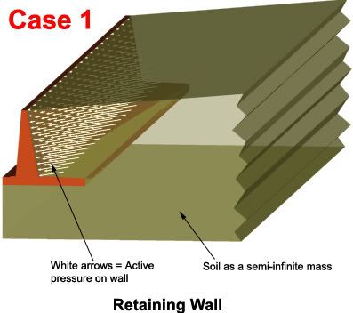
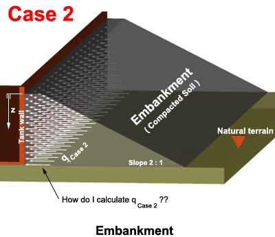
Is there any difference in the forces exerted on the walls by the soil (read: active pressure) when the tank is underground ([red]Case 1[/red]) and when it is above ground and the walls are earth-embanked (compacted soil embankment in [red]Case 2[/red]) ?

For example, a geotechnical report of a given soil states:
from a real soils report said:
[red]Horizontal Pressure on walls = Pa = 0.65 . ka . g . z[/red] , where:

[Pa] = [Kg/m2]
ka = 0.3
g = 1800 Kg/m3
z = depth
So, [red]Pa = 0.35 . z[/red]

Now, if I recall correctly, this relates to retaining walls or (underground walls for that matter) where the soil is a sort of a semi-infinite continuum, but how does it relate to an above ground embankment with a 2:1 slope as shown in [red]Case 2[/red] ?
Specifically, is there a drop in 'ka' in [red]Case 2[/red] ?

See figures:
Case1.jpg


Case2.jpg


Anyway, my common sense says that once you place compaction equipment, tractors, etc. on the embankment, the formula for 'Pa' above becomes completely useless.

Thanks.
 
Only if the structure can tolerate angular distortion (i.e., hinged at the foundation) on the order of 1 inch in 10 ft (2 inches in 20 ft, etc.) should you consider active earth pressures. For a tank, I'd base the earth pressure on the at-rest case. At rest earth pressures are typically 50 percent greater than active earth pressures.

I'm not familiar with the form of the expression that you provided in your quote from the geotechnical report. For me active earth pressure is based on tan^2(45-phi/2) - let's say about 0.33 for a typical soil. So you'd take the unit weight (120 pcf) and get an equivalent fluid density of about 40 pcf (0.65 g/cc). For the at-rest case, maybe you'd use 60 pcf (1 g/cc).

When dealing with sloping backfill, DM7.1 or DM7.2 (Navel Facilities Engineering Command - available on line for free) provides graphical solutions for the active case. I'd recommend that you solve the sloping backfill for the active case and then multiply that coefficieint by 1.5 to estimate the at-rest earth pressure coefficient. To use this graph, you need to know/estimate the friction angle. Now you just have to get a fix on the unit weight and voilla, you can solve the problem!

Regarding the use of compaction equipment I'd apply a "construction surcharge" to the calculated earth pressure. This construction surcharge would likely affect just the upper few feet. For the case that you have 10 ft of backfill (maybe that's too much?), the stresses of compacting the initial earth fill may not exceed the final earth pressures. However, as you compact the earth fill at the top, that's another story. Some folks recommend 90 to 92 percent compaction for soils adjacent to walls (i.e., overcompaction is not allowed) - just make sure that the soil will have sufficient strength for the intended slope angle.

Good luck. Thanks for the nice graphics, it really helps the discussion.

f-d

¡papá gordo ain’t no madre flaca!
 
Hello, I'm back again.

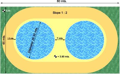
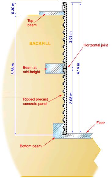
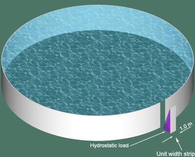
I'm having a difficult time estimating active and passive pressures from the sloping backfill for a project I'm currently working on. The project consists of two neighboring circular concrete tanks (Height=4.16m, Inner Diameter=26.10m, Wall Thickness=0.10m) with a compacted external embankment. As both tanks are identical, I've limited to only one of them the following study of the pressures involved.

Plan.jpg


The wall cross-section is like so:
tankcloseup.jpg


And the backfill is implemented like this:
Cross-section:
tankfull.jpg


Isometric view:
Iso2.jpg


I'd need clarification on some conceptual points that I don't fully grasp.
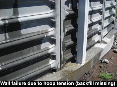
Earth backfill is what makes the whole system structurally sound. Precast panels are not stiff enough on their own to resist hoop tension or vertical bending moments. That's why the backfill becomes mandatory.

[tab]Sidenote:
See what happens when the contractor "forgets" to do the backfill:
wallfailure.jpg


Now to the calculations, could you please confirm if the following reasoning is correct?

Passive Pressure
==========

When the tank is filled, the backfill has the potential to counteract internal water pressure up to a maximum given by the passive pressure.
- OR -
To counteract hydrostatic load, the backfill can contribute a pressure whose upper limit is the value of the passive pressure.

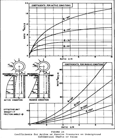
From ufc_3_220_10n.pdf, a "Unified Facilites Criteria" on Soil Mechanics by the Naval Facilities Engineering Command, page 223:

5. PRESSURE ON VERTICAL SHAFTS.
a. Shaft in Sand. In the excavation of a vertical cylindrical shaft granular soils, pressures surrounding the shaft approach active values. If outward directed forces from a buried silo move the silo walls into the surrounding soil, pressures approach passive values as an upper limit.

(1) Pressure Coefficients. See Figure 24 for active and passive pressure coefficients for a cylindrical shaft of unlimited depth in granular soils.
(2) Modification of Active Pressures. For relatively shallow shafts(depth less than twice the diameter), rigid bracing at the top may prevent development of active conditions. In this case, horizontal pressures may be as large as at-rest pressures on a long wall with plane strain in the surrounding soil. (See DM-7.2, Chapter 3.)
[attn]Reference:[/attn]
ufc_3_220_10n.pdf can be downloaded here.

So, if I'm on the right track I can use Figure 24 from that document to estimate the passive pressure that the wall would have to apply to the earth mass for the whole system to fail.

Figure24.jpg


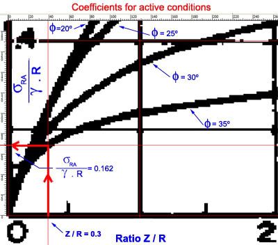
[φ] = angle of internal friction = 35º (backfill is a sandy soil ==> cohesion = 0)
[γ] = soil bulk unit weight = 1900 Kg/m3
R = external radius = 13.15 m
Z / R = 3.86 / 13.15 = 0.3

Then, from the passive pressure graph I get [σ]RP / ([γ] . R) = 3.25
PassivePressure.jpg


I must admit shallow cylinders like this tank configured an edge case for the graph author. I had to zoom-in and place rulers to get as accurate a reading as possible. (I don't know how valid the readings are for edge cases like this).

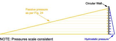
Anyways, going ahead: [σ]RP = 3.25 x 1900 x 13.15 = 81,201 Kg/m2
Here is the pressure diagram (scale consistent):

PassivePressureDiagram.jpg


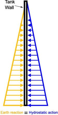
Obviously, by no means can the earth reaction be any different than the hydrostatic action. That was just an upper limit. It's as if the soil said "if needed, I can respond with pressures up to 81,201 Kg/m2". In other words, that number cannot be used in the calculations. When the system is in equilibrium, the actual diagram would tend to honor Newton's third law. Simplistically:

PassivePressureDiagramReal.jpg


However, these 81,201 Kg/m2 are half of the story. This number explains failure from the soil's point of view only. I think Figure 24 assumes that the underground cylinder can deform elastically whatever magnitude is necessary to push the surrounding soil up until 81,201 Kg/m2, the threshold that produces the soil's failure. That's not the case of a concrete wall. It's deformations what triggers concrete failure, not the stresses in the soil mass.
Let's see it from another angle:
Theoretically, the role of the sloping backfill in a thin-walled concrete circular reservoir is to prevent wall deformation, and thus the development of hoop tension and vertical bending moments that crack the concrete.

However, the more I think about this problem, the more complex the analysis gets (at least for me).
Let's rule out backfill for a moment.
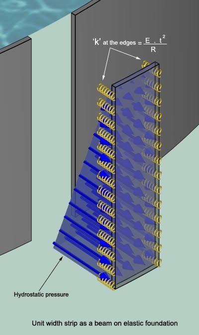
The specialized literature on tank design treats a circular wall subjected to hydrostatic pressure as a beam on elastic foundation. A strip of unit width is isolated and analyzed.
For the simple case in which no backfill is involved, the modulus of the foundation 'k' is E . t2 / R and the problem has a closed-form solution. Actions, reactions and deflections can be calculated easily.
(E = Modulus of elasticity of concrete, t = wall thickness, R = radius of tank)

BeamOnElasticFoundation.jpg


BeamOnElasticFoundationCloseUp.jpg


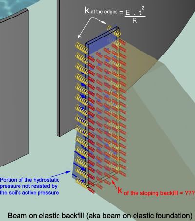
Now, how do I weigh the effect of the external backfill? Leaving compaction aside, I think the analysis is twofold:
Firstly, there's the at-rest pressure thing (P0 = 1.5 x Pactive) with its triangular loading diagram. If the at-rest pressure is smaller than the hydrostatic pressure, then the latter is counteracted by the former until the former runs out, so to say. The passive pressure then deals with the remainder of the hydrostatic pressure. More on this shortly. It could happen that the at-rest pressure is greater than the hydrostatic one. In this case even when the tank is full the walls will be compressed and the passive pressure never comes into play.

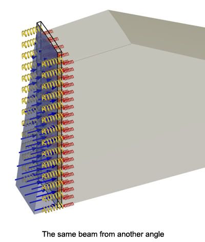
Secondly, back to the scenario where P0 < hydrostatic pressure. Here the walls start pushing into the backfill after the at-rest pressure is fully consumed, the wall then -I think- behaves pretty much like a slab on grade. Now we have a new player: the modulus of subgrade reaction 'k' of the sloping backfill that will participate in the equilibrium of the wall subjected to the portion of hydrostatic pressure not resisted by P0.

BeamOnElasticFoundationWithPassiveP.jpg


BeamOnElasticFoundationWithPassi-1.jpg


So, the first million dollar question is:
[COLOR=blue yellow]Does my convoluted reasoning make sense?
If so, what's the value of 'k' for the backfill ? Is it constant along the full height of the embankment?[/color]

Active Pressure
=========

Let's move on to some actual numbers from the present project:
To estimate the at-rest pressure I go back to the same Figure 24 cited above (active pressure graph):

ActivePressure.jpg


Then, Pactive = 4,048 Kg/m2
At-rest pressure = P0 = 1.5 x 4,048 = 6,072 Kg/m2

To me these numbers seem unrealistically high, but again I could be wrong.

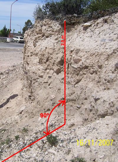
A 90º cut on the at-rest stockpiled soil that will be used for the sloping backfill suggests that active pressures, if any, can't be that big.

stockpile.jpg


Even more, the soil on the picture is naturally consolidated, not mechanically compacted as is common practice with sloping backfills.

So, the second million dollar question is:
[COLOR=blue yellow]What is the "real" active pressure?
4,048 Kg/m2 from Figure 24 ?
0 Kg/m2 like the photo suggests ?
Or something in between ?

Is it safe to use the graphs from Figure 24, even when short cylinders represent an edge case?
[/color]

Well...this got a bit longer than I'd thought.
Anyway, I'll greatly appreciate if someone can give me an opinion on the questions set above. That would really really help me with the project.

Before I finish...
I contacted a local geotechnical specialist with 20+ years experience to provide me some guidance but he was more clueless than me on this one. At one point I sensed he was embarrassed by my questions. He said his field of expertise (translation: comfort zone) was urban construction and related stuff like SPT's, etc. Go figure. [sad]

Thanks !
 
Status
Not open for further replies.

Part and Inventory Search

Sponsor