Continue to Site

Eng-Tips is the largest engineering community on the Internet

Intelligent Work Forums for Engineering Professionals

  • Congratulations waross on being selected by the Eng-Tips community for having the most helpful posts in the forums last week. Way to Go!

sizing a AC (drive) motor for a system that requires 3 separate outputs

Status
Not open for further replies.

Michael M Wilko

Mechanical
Oct 12, 2016
15
Hi, I was hoping someone could help me calculate the size of a drive to run the following,

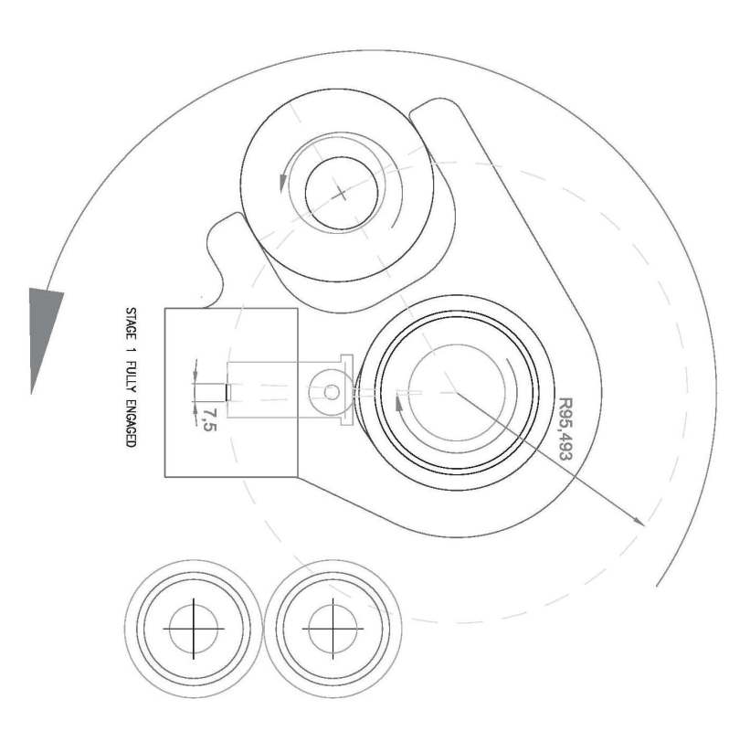
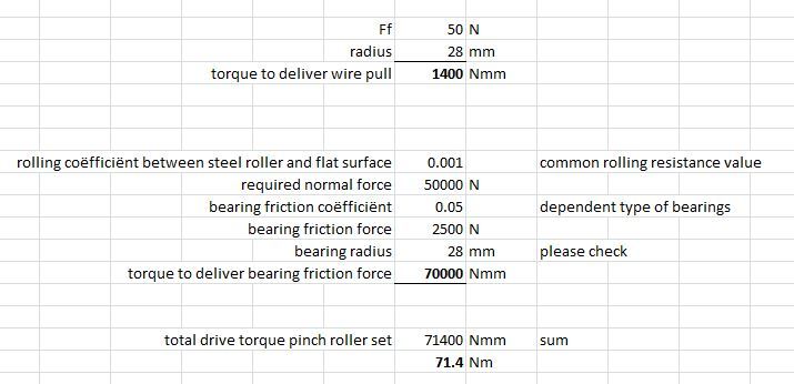
1. a pinch roller pulling a wire total force 50n, roller radius is 28.559, 100 rpm

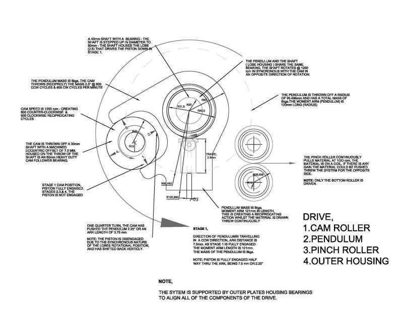
2. a lobe (cam roller bearing) swung off a shaft pushing a piston arrangement down, needing 100kg of force perpendicular to the shaft, shaft being 80mm diameter - with the lobe protruding 2.5 mm (42.5mm radius), the piston has a roller contact the lobe. the shaft is turning at 1200 rpm.

3. a cam spinning at 1200 rpm - throwing a pendulum anti & clockwise 2.5 degrees, ark length only 7.5mm - so 1200 is really 600 cycle clockwise and 600 cycles anticlockwise. the pendulums mass is about 8kgs, with a 120mm moment arm, some weight is around the bearing housing and some situate around the cam mouth which is on the same swing radius of approx 100 mm. the cam is set into a birds mouth arrangement.

I calculated that I would require 4 to 5 kilowatts approximately. i would use double sided timing belts to drive all axis from one motor with a servo drive

your help would stop many sleepless hours. if you can make sense of my question.

many thank s Michael
 
Replies continue below

Recommended for you

Hi,

Sounds like reciprocating masses so acc's en dec's hence fluctuating moments and power.
Please post a skeleton sketch where masses and work distances be seen.
So a moment curve per motorshaft rev can be figured out.
 
Hi jlnsol,

I am struggling to find a way to post the sketch, the area below for an attachement will not work for me.

Michael
 
Hi j,

for some reason I cannot get this to open my browser - must need to change something,

still trying
 
AC_drive_sizing_c1khui.jpg


well there you go - went thru and tried 4 only firefox has worked
 
Hi Michael,

Let's start with the pinch roller set. Is the 50N the pull force in the wire?
 
Capture_j54hx3.jpg


The force to drive the pinch set can be much higher because of bearing friction. See figures in this example calc.
 
Hi jinsol,

I would like to thank you for the help - I would be lost without it.

Using a hand held scale it took about 5kg to pull it.

I will take the time to write up a spec and re-post the drawing, might make thing easier having all info.

regards and thanks

Michael
 
Hi Micheal,

I can't read the text. Can you please upload the picture as an attachment instead of clipping into the post?
 
Thanks, it is clear now. I will look into it and get back to you.
 
good day j.many thanks, its is very complex and so different to the norm, I am thinking, hoping to use double sided timing belts to tie the 3 drives together, any thougts from your end.

regards
Michael
 
Hi Michael,

Just a few points to clarify if I understood this correctly:
A. pendulum arc travel distance at 95,5 mm radius is equal to the eccentric cam offset is equal to 7,5 mm
B. 7,5 mm arc at radius 95,5 mm is a pendulum swivel angle of 4,5 degrees
C. cam is rotating 1200 rpm, so there are 1200 clockwise and 1200 ccw swivel movements of the pendulum per minute
D. 1 cam rotation takes 0.05 seconds, so a clockwise pendulum movement of 4,5 degrees takes 0.025 secs and the ccw movement of 4.5 degrees takes another 0.025 sec being total 0.05 secs

Are you OK with these observations sofar?

Regards,
J
 
Hi J,

thanks for showing some interest in this contraption.

A. correct
B. correct
C. yes correct
D. again correct

All is observed correctly j.

I will have to check my notes, I think I have stated something wrong on the sketch - that you have made me aware of, the speed of the pinch rollers is wrong - maybe ??, I will look at it !!!!

regards

Michael

 
Hi Mike,

In the attached pdf you can see what I found to be the torque and power curves to drive the eccenter shaft for generating the pendulum swivel motion only.

Is this in your area of expectation?

This is another part of the total torque and power sum you're after.
J
 
 http://files.engineering.com/getfile.aspx?folder=58d2afd2-7f48-49dd-9d39-0648bee919b5&file=rocker_analysis.pdf
HI jinsol,

I will apologise for not responding earlier though your post did not reach me. Not sure why it has not hit my outlook -email.

what I have seen from the tables you have created is very correct.

thanks for your help and patience,

best regards Mike,

PS; I was wondering what was happening, hope all is good and will say thanks again
 
Hi Mike,

No problem! Understood.

Although I decided to quit posting to be honest...because of no reply at all.

Best regards,J
 
sorry to here that you have pulled the pin on this, your help was the only source I had to see this project move forward, if you ever change your mind I would be very appreciative of the assistance, as I have no skills in this field.
 
Status
Not open for further replies.

Part and Inventory Search

Sponsor