Continue to Site

Eng-Tips is the largest engineering community on the Internet

Intelligent Work Forums for Engineering Professionals

  • Congratulations 3DDave on being selected by the Eng-Tips community for having the most helpful posts in the forums last week. Way to Go!

Size andtemperature of compressed gas slug.

Prometheus21

Mechanical
Apr 22, 2023
112
Hello everyone,

As my knowledge on this topic is lacking, and I'm heavily in need of a refresher course; some input from you as well will likely be very helpful.

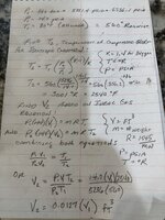
For the sake of discussion I am looking at simple system; a DN6 flexible polymer-lined flex-hose with a distance/volume piece (heat-sink) at the end. The hose is to be pressurized with 360 bar oxygen (99,5%) at 60°C at a timespan of 20 ms or less. In other words we are looking at an adiabatic compression; or gas hammer effect.

Now designing this heat-sink is rather important to contain the initial slug of gas; and the first compression event is the most severe one; as subsequent compressions does not achieve nearly as great a temperature as the slug that is initially present. A key feature in this configuration is that there is very little mixing of the two gas slugs (the initial slug and the incoming one). Mathematically this compression is usually treated as if a piston was performing the compression (located at the interface of the to gas slugs).

Now there are guidelines in designing a heat-sink with regards to the volume of the initial compression; the consensus being that a short, large-diameter distance piece can be functionally equivalent to a long small-diameter distance piece.

If the slug of gas reaches a high enough temperature then this can lead to ignition of contaminants or the hose itself; meaning the length of this hot slug must be contained.

How would one estimate (with a high level of accuracy):

1. The minimum required length for a given internal diameter D of the heat sink?
2. The volume of the hot gas slug?

Any input on pointers or references that might help me out here? I could always run CFDs but I need to get a firmer grip on the theory behind it.

Thank you.
 
Replies continue below

Recommended for you

This is NOT a simple system.....

Can you sketch this out a bit for us to understand what s going on as it looks vey transient and quite complex to me. How do you get two gas volumes (slugs is usually referred to as liquids in a two or three phase system. It is also a strange unit of something (force, energy ?).

A time span of 20 milliseconds is going to be so fast all sorts of strange things are going on, including how much your flexible hose expands / moves etc

So is the incoming gas at 360 bar / 60C or is this what happens after?

In generly you want to maximise surface area to increase or maximise heat transfer, but what is this heat sink made of? whatever, very little is going to happen in 20 mSec

Volume of the slug? No idea as you haven't described your system well enough.
 
To clarify: the system is simple compared to the systems actually seen in active filling stations for cylinders.

As for the sketch (rapid, simplified one):
1748352241869.png
A simple single-ended DPV - distance/volume piece is shown, connected to a hose.
Vu is the volume upstream of the flex hose including valve outlet, fittings ect.
Vh is the volume of the flex hose.
VDVP is the volume of the distance/volume region (heat sink + valve inlet, fittings ect. depending on what is connected - lets assume the majority of the heat shall be contained by the heat sink)

Slug in this setting refers to the "plug" of gas that occurs when rapid pressurization happens. The gas is compressed into a plug that will eventually reach the heat-sink.

Gas volume 1 (slug 1): the ambient volume of gas already in the hose.
Gas volume 2 (slug 2) : the volume that is released when the cylinder/ball valve configuration or similar opens and pressurization happens (typical ignition testing this is with 360 bar oxygen (99,5%) at 60°C, with an average valve opening time of 20 ms.)

Like stated in OP: A key feature in this configuration is that there is very little mixing of the two gas slugs.

"In generly you want to maximise surface area to increase or maximise heat transfer, but what is this heat sink made of? whatever, very little is going to happen in 20 mSec" - correct; the heat sink needs to be made of a very ignition resistant material; very often copper, nickel, monel or brass. The use of non-metals needs to be restricted and selected appropriately. The whole idea is to contain the volume of the warm slug of gas in the heat sink itself; so that the majority of the heat front do not come into contact with the hose (which contains non-metals).

I found a few good pointers in "FLAMMABILITY AND SENSITIVITY OF MATERIALS IN OXYGEN" volume 8, 9 and 13. Apparently the two main design ideas is to either contain the temperature increase; or contain the volume; but these are based purely on results of ignition testing. Guess I'm in for a lot of testing.
 
Well assuming the gas in the hose at t=0 is at atmospheric pressure? which "ambient" seems to mean? then the volume of the gas at 360 bar is going to be about 1/360th of the volume Vh+ VDVP. Soif the aim is to simply push this plug of gas out of the hose at what looks like close to sonic velocity and compress it at the far end then VDVP needs to be at least 1/360th of the total volume.

Then its pretty easy to work out length vs diameter, but note that the surface area is key to how long it then takes for the heat to dissipate.

Oh and its not usually possible to "estimate (with a high level of accuracy". Those are two different things.... Especially with such a transient thing going on.

BTW I would love to know which valve opens in 20msec....
 
The calculation needs to also consider the increase in temperature due to an isentropic compression of the slug. First use isentropic gas compression to find T2 = compressed gas temperature. Then use ideal gas equation to find compressed volume V2. See attached calculation.
 

Attachments

  • IMG_2249.JPG
    IMG_2249.JPG
    1.4 MB · Views: 17
I forgot to include the compressibility factor "Z" for oxygen at P2/T2 which will be significant. This will be a number less than 1.0. For such high pressure and temperature it may even be about 0.5. In this case:

P2(144)V2=ZmRT2

Since P1/T1 is ambient the Z = 1.0 for initial conditions.

So when combining the two ideal gas equations and solving for V2, the answer shown of (0.0127)V1 will really be Z(0.0127)V1. If you omit the compressibility factor then you will just get a conservative result.
 
Actually I see now that for very high pressure and temperatures above what's called the critical pressure and temperature the compressibility can actually be as high as 1.1 to 1.3 so it needs to be included in the calculation as the actual required volume may be greater than the ideal.
 
LittleInch: in this setting (filling station) the definition of ambient will be standard condition, 15.00 °C; 59.00 °F) and 101.325 kPa.

Having talked to a test engineer at Air Liquide CTE they recommend designing the system to contain 1/8th of the volume Vh+ VDVP; as a rather conservative "better safe than sorry". Asking why I was simply informed that systems that allow for this amount of hot slug volume containment do not ignite nearly as often as systems who don't; and any ignition that might occur is deemed to be due to contaminants present in the system; leading to a kindling chain.

"Oh and its not usually possible to "estimate (with a high level of accuracy". Those are two different things.... Especially with such a transient thing going on." - I agree; my original sentence was inaccurate and wrong.

"BTW I would love to know which valve opens in 20msec" - Custom ball valves with rotary solenoid actuators typically reach 10-20 ms opening times. Now one laboratory setup I have seen uses a custom Lee Company high-speed solenoid valve to reach a 1.4 ms opening time. 0.25 ms is possible; but then you have trade-offs between the speed, flow capacity and pressure rating.

Snickster: Yes, this equation is used in every oxygen design handbook I have ever read. It describes the worst case scenario (and temperature), and is a good worst-case estimate. Luckily you will never reach those temperatures in real-life; but it will still be high enough to ignite most metals and non-metals alike; especially with contaminants being present; leading to a kindling chain.

Now the test engineer actually stated something rather interesting; that in his experience while the volume of the heat-sink is important; the geometry of the inlet and outlet where the gas enters and exits play a large part in how ignition resistant the system is. It seems that the higher curvature/rounding you have in relation to the inner diameter of the inlet/outlet connection gives a higher ignition resistance - in other words avoid sharp 90° edges. Which goes back to what LittleInch said about high level of accuracy not being (usually) possible with such a transient thing going on.
 
I found a chart for the compressibility factor of oxygen up to 1000 K. The maximum at 5236 psia or 36,100 kPa is about 1.07. However the actual temperature is 1666 K so it will be somewhat higher. I think you will be ok if you just use Z = 1.3 or even Z = 1.5, but you should try to find chart with temperature up to 2000 K to make sure.
 

Attachments

  • Oxygen Compressibility Factor.docx
    96.4 KB · Views: 5
Snickster:

Correct; the Z factor is important. Yet to estimate T2 the Z factor is usually omitted so that a conservative result is used as basis for design (like you say).

That brings up another question; is there any official diagrams for the compressibility factors given different gases? I have until now used good old hard-copy versions from decades ago...
 
Good catch! I will be honest and say I assumed the Z-factor would be < 1.0 as I usually operate in that area - shows you what I now of the subject...
I only have charts up to a 1000K available so time to start searching for extended charts
 
I just caught a mistake in my calculation. T2 in the equation solving for V2 should be 3001 deg. R, not 2540 deg F.
 
Rather than work out what T_isen will be at 360bar with a constant Cp/Cv or gamma value, given the large compression ratio, it would be better to read off what T2 will be with a T-S diagram for O2 - see fig 2-15 on page 2-263 in the 7th edn of Perry. So you dont have to worry about Cp/Cv and Z values changing as P and T rise. But this graph goes no higher than 340bar.

PS : I've just seen this T-S graph for O2 in Perry goes only up to some 310degK, so it is of no use in this application.

With the NIST thermo properties prediction program available on the internet, I get T2_isen = 1320 degK (or 2376 degR) at P2 = 360bar. P1 = 1bar, T1 = 290degK. Density at 360bar = 3.03gm moles/ litre
 
Last edited:
LittleInch: in this setting (filling station) the definition of ambient will be standard condition, 15.00 °C; 59.00 °F) and 101.325 kPa.

Having talked to a test engineer at Air Liquide CTE they recommend designing the system to contain 1/8th of the volume Vh+ VDVP; as a rather conservative "better safe than sorry". Asking why I was simply informed that systems that allow for this amount of hot slug volume containment do not ignite nearly as often as systems who don't; and any ignition that might occur is deemed to be due to contaminants present in the system; leading to a kindling chain.

"Oh and its not usually possible to "estimate (with a high level of accuracy". Those are two different things.... Especially with such a transient thing going on." - I agree; my original sentence was inaccurate and wrong.

"BTW I would love to know which valve opens in 20msec" - Custom ball valves with rotary solenoid actuators typically reach 10-20 ms opening times. Now one laboratory setup I have seen uses a custom Lee Company high-speed solenoid valve to reach a 1.4 ms opening time. 0.25 ms is possible; but then you have trade-offs between the speed, flow capacity and pressure rating.

Snickster: Yes, this equation is used in every oxygen design handbook I have ever read. It describes the worst case scenario (and temperature), and is a good worst-case estimate. Luckily you will never reach those temperatures in real-life; but it will still be high enough to ignite most metals and non-metals alike; especially with contaminants being present; leading to a kindling chain.

Now the test engineer actually stated something rather interesting; that in his experience while the volume of the heat-sink is important; the geometry of the inlet and outlet where the gas enters and exits play a large part in how ignition resistant the system is. It seems that the higher curvature/rounding you have in relation to the inner diameter of the inlet/outlet connection gives a higher ignition resistance - in other words avoid sharp 90° edges. Which goes back to what LittleInch said about high level of accuracy not being (usually) possible with such a transient thing going on.
That's quite a big conservative volume but for such a rapid and violent thing you're doing it will probably need something to allow a bit of mixing and temperature dissipation.

The non sharp edge sounds a bit like Hydrogen vents where they apparently use a toroidal edge to things likes vents. You may want to have a reducer increasing size at the end of you hose to mix the gas up a bit more.
 

Part and Inventory Search

Sponsor