Hello SH,
From your input:
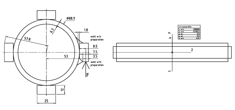
At M=20 kNm, if divided by 4*56 kN, you assumed the acting radius to be equal to the dia. of the pipe. But you need to relate the radius to the application point of the force onto the plates, so F imo should be 20/(4*0.053)=94,3 kN.
If welded w/o preparation the plate would have an important gap to the pipe, this should be avoided --> Assumed weld preparation as drawn, a weld to be 4.5 mm. Shear for one plate would arrive at approx. 63 N/mm². Assuming applicability for your utilization of standard FEM 2.132 (conveying machinery), the permitted statical shear stress at fillet welds for common / main loads is approx. 275/235*113 = 132 N/mm². Concluding: At least 2 of the 4 plates need to be load bearing.
Imo bending action should not be neglected, to the effect of a von-Mises stress of approx. 129 N/mm², to the same effect as said above.
Yes, you could have a stronger pipe than that, but with thicker walls + thicker welds, the loadbearing capac. of the fillet weld shall decrease too. Limit: t. b. sought / t. b. clarified.
However, if your load is rather cyclic / alternating, fatigue strength limits would apply, these being drastically lower than those mentioned above.
Now, as desertfox & Tmoose point out, there's little probability that with a welded design the plates shall arrive at an equal distribution of forces.
Alternatives:
- to manufacture the item from a dia. 120 mm block material of sufficient strength, and to tune size, shape + position tolerances of the driver and the mating hub
- to use a keyed / splined shaft profile
My request:
For this issue, please seek the support of a mechanical engineer who could responsibly design the drive considering all (unknown to us here) parameters. I gather there's more to it than the above input.
Regards
R.
9.3. ambiguity deleted