StrEng007
Structural
- Aug 22, 2014
- 543
This is a long one with lots of questions...
I'm trying to determine the advantage/disadvantage between two different types of lateral systems on a 2-story building with a CMU/Concrete Tie-Beam shell. Both buildings use a stem wall type foundation where top of footing is located 1'-4" below grade. My issues are specifically to do with the 1st floor and supporting foundation.
The building experiences high winds, no seismic, and is built on non-cohesive soils (sand). Shallow foundations are the accepted practice.
System #1:
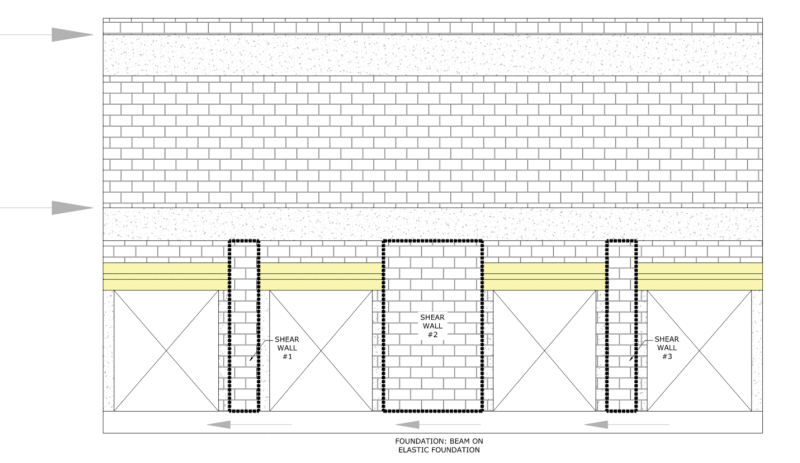
The first floor is comprised of three shear wall segments made from reinforced CMU. Unfortunately, the wall openings don't allow for balanced proportions of each shear panel and the middle segment takes on a majority of the lateral loading. Each shear wall ties to a 24" deep concrete tie beam at the 2nd floor diaphragm. When determining the lateral force distributions for each shear panel, I utilized the approach where the top of the wall is considered to be fixed (Relative Rigidity of Fixed Walls/Piers). The headers at each opening are framed with pre-cast lintels that allow for a modular system and alleviate some need for formwork.
The foundation is a shallow wall foundation modeled as a beam on elastic foundation. After carrying down all my gravity loads and lateral loads, this wall footing ends up being much larger than I anticipated. Part of the issue, from my understanding, is due to the elastic beam not 'being allowed' to have any tension along it's length. Understanding that soil cannot resist tension loading (performed via Enercalc) the foundation either conservatively works or doesn't work at all.
System #2
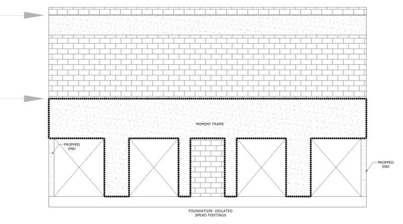
The second system considers four individual beam-columns that are monolithic to a portal frame that supports the 2nd floor/roof. My approach is to design the portal with pinned bases to alleviate some of the moment imparted to the top of foundation. This approach yields isolated footings that are easier to digest than the large wall footing required for system #1.
Although system #2 provides more desirable foundations, I'm not sure how reasonable my design assumptions are. The questions I'm trying to answer for myself are:
1. Is there an alternate way to design the foundation for system #1? I tried looking at each shear panel with an individual spread footing, but the footprint gets so long that they all merge together. Also, shallow foundations will be the only accepted approach as far as the GC/construction. Deep foundations are out of the question.
2. How reasonable is it to assume that system #2 will achieve pinned bases? I typically fully develop all vertical bars with equivalent hooked bars placed in the foundation. Logic tells me that each beam-column is neither fully pinned or fixed. Without the aid of advanced FEA software, how do I rationally go about determining what's actually happening? I've seen a lot of engineers call a concrete column pinned at the base but still shown full development of bars.
3. For system #2, if the middle segment of infill CMU is not isolated from the concrete with some sort of joint, will it become a shear wall segment? My details typically consider the horizontal joint reinforcing (ladder joint) to be continuous into the adjacent concrete column. The shell contractor will erect CMU first, then pour the concrete columns against the existing CMU.
4. For both systems, how do you all handle the out of plane loading requirements while designing your MWFRS lateral systems. My understanding of ASCE 7 requires dual loading on these walls. Let's say this LFRS line is carrying transverse wind loading, then logically there would be side wall loading the shell/doors/windows with out of plane negative flexure/shear.
5. I see a lot of building similar to this where I practice... most of which would have utilized a 24" wide x 12" wall footing (Allowable soil bearing 3,000PSF). I'm not sure what approach these engineers are taking, short of ignoring the lateral demand all together. For a location that experiences such high winds, I'm often surprised at how small the foundations are. Similarly, how often chord steel requirements are not called out on CMU shear walls.
I'm trying to determine the advantage/disadvantage between two different types of lateral systems on a 2-story building with a CMU/Concrete Tie-Beam shell. Both buildings use a stem wall type foundation where top of footing is located 1'-4" below grade. My issues are specifically to do with the 1st floor and supporting foundation.
The building experiences high winds, no seismic, and is built on non-cohesive soils (sand). Shallow foundations are the accepted practice.
System #1:
The first floor is comprised of three shear wall segments made from reinforced CMU. Unfortunately, the wall openings don't allow for balanced proportions of each shear panel and the middle segment takes on a majority of the lateral loading. Each shear wall ties to a 24" deep concrete tie beam at the 2nd floor diaphragm. When determining the lateral force distributions for each shear panel, I utilized the approach where the top of the wall is considered to be fixed (Relative Rigidity of Fixed Walls/Piers). The headers at each opening are framed with pre-cast lintels that allow for a modular system and alleviate some need for formwork.
The foundation is a shallow wall foundation modeled as a beam on elastic foundation. After carrying down all my gravity loads and lateral loads, this wall footing ends up being much larger than I anticipated. Part of the issue, from my understanding, is due to the elastic beam not 'being allowed' to have any tension along it's length. Understanding that soil cannot resist tension loading (performed via Enercalc) the foundation either conservatively works or doesn't work at all.
System #2
The second system considers four individual beam-columns that are monolithic to a portal frame that supports the 2nd floor/roof. My approach is to design the portal with pinned bases to alleviate some of the moment imparted to the top of foundation. This approach yields isolated footings that are easier to digest than the large wall footing required for system #1.
Although system #2 provides more desirable foundations, I'm not sure how reasonable my design assumptions are. The questions I'm trying to answer for myself are:
1. Is there an alternate way to design the foundation for system #1? I tried looking at each shear panel with an individual spread footing, but the footprint gets so long that they all merge together. Also, shallow foundations will be the only accepted approach as far as the GC/construction. Deep foundations are out of the question.
2. How reasonable is it to assume that system #2 will achieve pinned bases? I typically fully develop all vertical bars with equivalent hooked bars placed in the foundation. Logic tells me that each beam-column is neither fully pinned or fixed. Without the aid of advanced FEA software, how do I rationally go about determining what's actually happening? I've seen a lot of engineers call a concrete column pinned at the base but still shown full development of bars.
3. For system #2, if the middle segment of infill CMU is not isolated from the concrete with some sort of joint, will it become a shear wall segment? My details typically consider the horizontal joint reinforcing (ladder joint) to be continuous into the adjacent concrete column. The shell contractor will erect CMU first, then pour the concrete columns against the existing CMU.
4. For both systems, how do you all handle the out of plane loading requirements while designing your MWFRS lateral systems. My understanding of ASCE 7 requires dual loading on these walls. Let's say this LFRS line is carrying transverse wind loading, then logically there would be side wall loading the shell/doors/windows with out of plane negative flexure/shear.
5. I see a lot of building similar to this where I practice... most of which would have utilized a 24" wide x 12" wall footing (Allowable soil bearing 3,000PSF). I'm not sure what approach these engineers are taking, short of ignoring the lateral demand all together. For a location that experiences such high winds, I'm often surprised at how small the foundations are. Similarly, how often chord steel requirements are not called out on CMU shear walls.