Tek-Tips is the largest IT community on the Internet today!

Members share and learn making Tek-Tips Forums the best source of peer-reviewed technical information on the Internet!

  • Congratulations TugboatEng on being selected by the Eng-Tips community for having the most helpful posts in the forums last week. Way to Go!

Shear stresses in a node

Status
Not open for further replies.

isok89

Civil/Environmental
Joined
May 9, 2016
Messages
37
Location
NL
Greetings all,


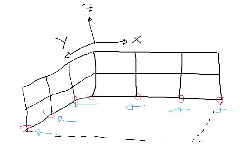
How do I determine the shear stresses in a node of a SR4 element?
Given in the image below.

I tried S12 but the results I get are unclear.

Knipsel_yufsgh.jpg


Thanks in advance
 
What is unclear? S12 are the in-plane shear stresses. Use a symbol or material orientation plot to check what the local orientations of the elements are.
 
Shell stress results may be confusing since there are special rules regarding this element output. Most importantly, Abaqus projects and rotates the coordinate system (global or local) on the shell surface in such manner that Z axis is always coincident with shell’s normal vector. Stress in this direction is always zero.

There are also special purpose output variables for transverse shear stress components in shells called TSHR. You can request them before the analysis.

One more thing - you should be familiar with shell section points too. You may have to change the default top/bottom plotting if you want transverse shear stress values other than zero.
 
Status
Not open for further replies.

Part and Inventory Search

Sponsor

Back
Top