Continue to Site

Eng-Tips is the largest engineering community on the Internet

Intelligent Work Forums for Engineering Professionals

  • Congratulations KootK on being selected by the Eng-Tips community for having the most helpful posts in the forums last week. Way to Go!

Shear Plate Length/Bending 6

Status
Not open for further replies.

BTRussell

Structural
Feb 4, 2014
7
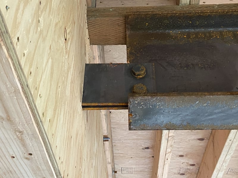
I have a project where a contractor did not install a beam and shear plate as noted in the plans. Instead of a shingle shear plate with three bolts attached near a support beam, the beam is supported by double shear plates with two bolts, and the beam is about 6" off of where the support beam is located.

I've run some calcs and I think that the bolts and plates work, just wondering if there is some maximum length for shear plates before some specific equation has to be checked. This is on a residential project and I designed it for full live loading and snow loading (200 psf) at the same time, but the deck is covered and I don't think that the beam will ever see the load it was designed for, let alone the LRFD factored load amounts. Plates are 7" deep & 7/16" thick, two 1" diameter bolts acting in double shear. Service level loading designed for about 1k D / 3k L / 12 k S at beam end.
Shear_plate_pqf9lc.jpg
 
Replies continue below

Recommended for you

That's a whole other question...[ponder]

Rather than think climate change and the corona virus as science, think of it as the wrath of God. Feel any better?

-Dik
 
Does not appear to be any bolts between the top flange and wood plate.
 
...and why preserved wood or fire treated? Scrap? If PT, you might want to use HDG or SS fasteners.

Rather than think climate change and the corona virus as science, think of it as the wrath of God. Feel any better?

-Dik
 
Tough to accept but dismantling what's there I'm not sure is an option, unless it doesn't work. From what I'm seeing, even in the white papers, the connection should work.

All the steel should have thread rods and nuts which connect the wood plates to the steel members btw, not really an issue there.
 
That is a very large amount of eccentricity. I ran some calcs (see attached), and it appears like the controlling limit state is tearout at the beam. I made a lot of assumptions about beam size and edge dimensions, so you'll need to check it for yourself, but it appear to not even be close (Stress Ratio = 4.16).

Structural Engineering Software: Structural Engineering Videos: www.youtube.com/structuralcentral
 
Very helpful, thanks @programmingPE. I will look into this limit state. Seems like if it is controlling, I can have them weld a vertical plate to the beam web to prevent tearout. Should help with some of the unsightliness as well.
 
The shear plate doesn’t appear to meet the commonly accepted minimum depth of T/2 required for rotational restraint at the support, so I’d look at quantifying that before accepting the connection.
 
So looking at Programming's calcs and the AISC manual, I think that the bolt tearout strength should be the sum of the bolt tearout capacities, seems like the calculations only take into account 1 bolt. Multiplying by two obviously helps. If I add back the 1/4" used conservatively for overruns and use 0.345" for web thickness rather than 1/4" I'm at about 9k per bolt or 18k total (LRFD) or 12k (ASD). This # is still less than the factored load, although I never see it really taking 12kips of snow. Thinking about having them weld a 4" or 5" wide vertical steel plate to the web with a partial pin and adding two bolts in this to the existing shear plates. I'm going to have them open up the wood plywood around the plate/support connection as well and see if we can maybe get another set of double shear plates on.

Thanks for all your help guys!
 
You don't get to multiply the tearout capacity by two. The Bolt Group Coefficient, C, tells you what the force will be in the critical bolt based on the applied load (C = Applied Load / Maximum Bolt Reaction). When your maximum permitted shear load of 5.3 kips is applied, the force in the critical bolt will be 5.3 kips / 0.506 = 10.5 kips which equals your tearout capacity (0.75*13.9 kips).

(You may have seen examples where bolt shear controls and the total capacity of the bolt group is always C*Bolt Shear Capacity. You never multiply this by the number of bolts.)

If you look at Example II.A-19B in AISC's Companion to the AISC Steel Construction Manual, they have an extended single-plate connection that is actually controlled by tearout, just like your case, and they do not multiply the capacity by the number of bolts. See the screenshot below.

AISC_Design_Example_II.A-19B_-_Tearout_Controls_for_Extended_Plate_d4swau.png


Structural Engineering Software: Structural Engineering Videos:
 
Assuming the tabs connect mid depth of the support beam I would be interested in the web thickness of the support beam. PPE's example is a rigid support. Regardless, seems like they need repairs.

bolt-tab_pd2k8e.jpg
 
Very good, thanks again Programming.

Brad, the shear tabs are welded to a web stiffener in the support beam.
 

T/2? I'm not sure of this requirement.

Rather than think climate change and the corona virus as science, think of it as the wrath of God. Feel any better?

-Dik
 
The bottom bolt will rip out the back of the web.
 
slip critical? [ponder]

Rather than think climate change and the corona virus as science, think of it as the wrath of God. Feel any better?

-Dik
 
Status
Not open for further replies.

Part and Inventory Search

Sponsor