StrEng007
Structural
- Aug 22, 2014
- 545
I got a question that's come up regarding the theory behind how shear flow works. Considering a simple span beam with uniform loading. I've always used the following to explain shear flow.
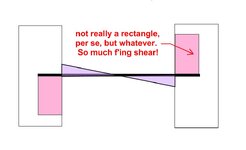
The chord force of the beam is the area under the shear flow diagram. Said in a different way, shear flow is the accumulation of shear stress that results in the chord force due to moment.
Equations:
V = wL/2
M= wL²/8
Shear Flow = VQ/I
Chord force in the beam section = the area under the shear flow diagram = (VQ/I) x L/4
Putting some numbers behind it. Take a 8"x12" rectangular cross section:
I = 1152 in^4
Q = 144 in^3
w = 100 lb/ft, L= 10ft
M = 1250 lb-ft or 15,000 lb-in
V = 500 lb
Chord force illustrated by shear flow:
Shear Flow = 62.5 lb/in
Chord Force = 62.5 lb/in x (120 in/4) = 1,875 lb
Chord force illustrated by bending stress:
Bending Stress = 15,000 lb-in (6 in)/ 1152 in^4 = 78.125 psi
Chord Force = 78.125 psi x (8in)(6in)x1/2 = 1,875 lb
However, this theory doesn't work when applied to a single span beam with fixed end conditions. The shear at the end of this beam would be the same as the simple span beam shown above. However, we know that using the area under this shear flow diagram would NOT be equal to the maximum chord force produced by the moment.
So the question is, when you have a fixed end single span beam, is shear flow calculated in the same exact manner? If so, how do you explain how to derive the chord forces in relationship to the shear flow force?

