Tek-Tips is the largest IT community on the Internet today!

Members share and learn making Tek-Tips Forums the best source of peer-reviewed technical information on the Internet!

  • Congratulations TugboatEng on being selected by the Eng-Tips community for having the most helpful posts in the forums last week. Way to Go!

Shaft spline

  • Thread starter Thread starter Phizinza
  • Start date Start date
P

Phizinza

Guest
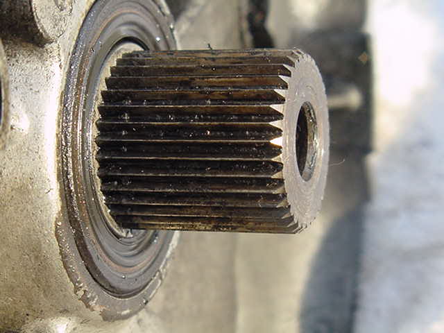
Hi, I'm drawing a stub axle for a car (it's the part that connects the differential to the axle). It is short and has two splines on each end. Now I gather you don't need a spline drawn in the cad drawing as the spline cutter manufactures use doesn't use the drawing. But I would like to have something there just to show it is splined. Is there any easy ish way to draw a spline around the shaft?

Thank you
 
sorry.. not able to get what u r trying to ask... can put
some pic of what do u want actually..
 
Something like
spline.JPG


And this
IM001061.jpg
 
For least memory you could simply have lines and an annotation, stating that it is splined with dimensions on the call out. If you want to actually draw it, use the circular pattern tool.
 
1. Sketch a triangle on the endface of the shaft (either to remove or add material).


2. Extrude the proper depth


3. Circular pattern it, using the axis (or temp axis) of the existing shaft as the reference.


4. Save the part
 
You could show a small area of the spline drawn on to your 2D views though I would think it would be just as easy to do what Jim Shaw has suggested.
 
Brilliant jim! Thanks for that idea.
 
no prob, glad to help!
 

Part and Inventory Search

Sponsor

Back
Top