Tek-Tips is the largest IT community on the Internet today!
Members share and learn making Tek-Tips Forums the best source of peer-reviewed technical information on the Internet!
-
Congratulations JAE on being selected by the Eng-Tips community for having the most helpful posts in the forums last week. Way to Go!
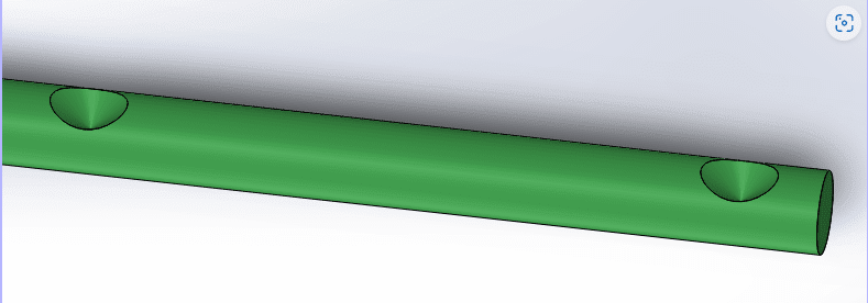
Countersink Bit on a shaft 1
- Thread starter saad.mech
- Start date
![[pc2]](/data/assets/smilies/pc2.gif "[pc2] [pc2]")