Continue to Site

Eng-Tips is the largest engineering community on the Internet

Intelligent Work Forums for Engineering Professionals

  • Congratulations 3DDave on being selected by the Eng-Tips community for having the most helpful posts in the forums last week. Way to Go!

Shaft Failure in Translation Gear Reducer of Bucket Wheel – Need Help Identifying Cause

fairyfales

Student
May 28, 2025
7
I’m working on an engineering project analyzing the cause of repeated shaft failure in a translation gear reducer that drives a support wheel of a 400-ton bucket wheel excavator.

System Details

  • Shaft material: 42CrMo4
  • Motor power: 5.5 kW , n=1000 t/min
  • Reducer output power: 4 kW
  • Gear ratio: 150:1
  • Number of support wheels: 16
  • Each shaft supports 1 wheel (load ≈ 25 tons)
  • Bearings: 2 cylindrical roller bearings
  • Support wheel diameter: 710 mm
  • Translation speed: Varies between 1.5 mm/min and 15 mm/min
im a bit lost on the calculus , can someone assist me with approaches i should follow and calculus i have to made ? ( it usually breaks from the spline section) 1748440145818.png
 
Replies continue below

Recommended for you

Are the support wheels friction drive on the bucket chain or are is it a sprocket or some other type of direct drive?
 
Out of the 8 assemblies, does the shaft always break at the same assembly location?
That is, perhaps always the first in line?
 
OP: Examine the exposed surface of the failed piece - and the exposed surface of the other section not shown in your photo, if available.
Determine the failure mode (ductile or brittle) and method (tensile, torsion, or bending).
What causes specific combinations of mode and method? Usually, force applied in some fashion. What force(s) are being applied - and where?

Now look at the geometry - are there areas where the effect of the force is amplified? Why? Where? How?

How much force - applied in what manner - is needed to achieve a result that matches what you can see of the failure?

Then answer some additional questions: is it geometry dependent? Force dependent? Number of cycles? Material dependent? Environmentally dependent (temperature, humidity, altitude, etc.)?
 
There are possible mechanical issues that me cause loading in excess of design loading.
If the anchor of one gear-box is out of adjustment that my cause excess loading.
Wear in the pins and bushings of the bucket chain may cause excess loading if the gearboxes are not adjusted as the pins and bushings wear.
Wear in the pins and bushings of the bucket chain may cause a change in pitch that will cause excess loading.
Possible remedies:
Check the actual pitch of the bucket chain.
Check the actual pitch of the sprockets.
Do a current graph of each drive motor. Looks for high peak currents as the sprocket contacts and starts to drive the chain.
Compare the drive currents.
The actual currents are not as important as are unequal currents and fluctuations.
 
Where is the chain? I've been a big fan of wheel bucket excavators and I have not detected the presence of a chain in the wheel drive.

I expect there to be segments to the rim in smaller designs but it doesn't appear to flex as a chain would:

 
Where is the chain?
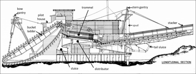
Sorry, I was visualizing a ladder type dredge.
Screenshot 2025-05-30 at 17-27-12 Canadian Klondyke Mining Company Dredge No. 4 – CSCE _ SCGC.png
I see now that this thread is in regards to the walking tracks.
If you replace "Bucket Chain" with "Track Chain" in my posts, they will mostly be valid.
 
Last edited:
The start of the analysis is talking with the stress engineers in the company. There should have been a stress analysis done before the part was made. The next step is talking with the metallurgist who selected the material and whoever is in QA/QC that accepted the material certification for the part. This will include the alloy as well as any post-machining heat-treat, surface hardening, tempering, possibly nitriding or some other finalizing step.

There are plenty of shaft analysis books that cover bending, shear, and stress concentration factors as well as resources for material properties.

Offhand it looks like a sudden sharp in section properties that forms a stress concentration for torsion, as well as a creating a stress concentration for bending loads, exaggerated by the tiny top surfaces of the spline.

This is the classic method of adding a small feature to a relatively large section that increases the distance to the outer fiber without increasing the resistance to bending. Since strain is taken as linear from the bending neutral axis this increases the strain in the outer fiber without increasing the bending load to do it, making for a location that is prime to crack from the most microscopic scratch or other defect.

I expect that every crack starts at the top of each tooth and they progress to joint at the root.

It's not so much a design analysis that is required as it is a design detail to be avoided.

But I cannot tell all of what to avoid because there is far too little information given.
 
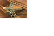
It may be a matter of semantics, but I think the wheel shaft may likely be from a bucket wheel stacker/reclaimer, which runs on rails along a fixed path.


bucket wheel  reclaimer.png
 

Part and Inventory Search

Sponsor