Continue to Site

Eng-Tips is the largest engineering community on the Internet

Intelligent Work Forums for Engineering Professionals

  • Congratulations waross on being selected by the Eng-Tips community for having the most helpful posts in the forums last week. Way to Go!

semi-rigid Diaphragm forces + RISA3D

Status
Not open for further replies.

CitizenEngineer

Structural
May 17, 2022
1
thread507-461673

I was looking for a solution to this question and this thread seemed to be headed in that direction, but apparently it was some kind of marketing scheme from RISA... I couldn't tell, or maybe there was a comment that was removed that I could no longer see. Either way, does anyone have an answer to the question in this thread? My office has RISA 3D and RISA Floor (recently purchased, so still learning the ropes) and it would be pretty handy to be able to pull the diaphragm forces out for deck fastener design.

Thank you in advance.
 
Replies continue below

Recommended for you

Okay RISA Floor has a diaphragm module that supposedly can run the diaphragm checks per NDS. In order to use that feature you must use RISA FLOOR and properly identify the diaphragm regions, I don't know how (or if at all) this works with semi rigid diaphragms or just uses the flexible approach. Outside of that you can do a section cut of the floor plates nearby a shear wall, you can extract from that the shear along the section cut do check the diaphragm manually. I summon Josh Plumb to help you more.
 
First, my caveat / bias statement. I worked for RISA for 16 years under the original owner and was forced out when Nemetchuk bought out the company in late 2017. And, I remain somewhat resentful of the new RISA management for the way they treated me (and for what they've done to the company since then!). I now work for one of their main competitors (CSI which is famous for SAP / ETABS and such). Ergo, I have plenty of reasons to be biased against RISA. Therefore, please interpret my opinions accordingly.

RISAFloor and RISA-3D can work together for rigid, semi-rigid or flexible diaphragms, though it has been almost 5 years since I have done this myself. From what I remember, the "design" of wood diaphragms was always marketing feature that never really worked. It might have worked for a perfectly rectangular diaphragm boxed on all sides by lateral force resisting frames or walls.

Regardless, the real focus was to get the ANALYSIS and force distribution of the diaphragms correct. Meaning that the later forces were correctly distributed to any drag or collector members and then distributed into the lateral force resisting system. This, if I recall correctly, worked pretty well. There were a couple of things to remember:
a) You had to make sure your drag struts / collector elements and such were modeled in 3D. Otherwise, the force distribution could get messed up.
b) If you had a sloped floor (like a hip and gable wood roof) then I don't remember exactly how the flexible diaphragm behavior worked.... or if it worked at all. They may have some documentation on that to see how to get that to work better. I just don't remember.
 
Using semi-rigid diaphragms with Floor>3d models - I typically just find the total force being delivered to the frame+collectors/shearwalls/etc and divide it by the length of the frame+collector/shearwall to get diaphragm shear. Dealing with the force summation tools can be a little convoluted so I K.I.S.S.

As driftLimiter mentioned, there used to be functionality that would allow the program to actually design the wood diaphragm regions (sheathing, nailing patterns, chords, etc). It would work fairly well for very simple structures where you could easily define rectangular wood diaphragm regions, all of which must be bounded by lateral members/walls. BUT......ever since the new (.NET) version of risa 3d was released this functionality is no longer available. You can still define diaphragm regions to help guide the program when assigning flexible diaphragm 'spans', or just let the program sort it out by itself. When using flexible diaphragms you can view the applied diaphragm shears in risa 3d by viewing loads>basic load cases>transient area loads (the program will create additional basic load cases at the end of the list of basic load cases and that is where you'll find the resulting flexible diaphragm shears). Flexible diaphragms are simply a load distribution mechanism. There's a good deal of discussion about this in the manuals.
 
I am trying to use RISA-Floor>3D to analyze a large and irregular wood diaphragm on a 5-over-2 wood podium building. I have a lot of cantilevered areas of the diaphragm (meeting the limits of the SDPWS 2015) so I need to model the diaphragm as semi-rigid. I am struggling to find any information on how to input (convert?) the Ga values (kips/in) from table 4.2A to E & G (both ksi). The default values for "gen_plywood" in RISA are E=1800 ksi and G=38 ksi. Where do these numbers come from? Any suggestions?
 
DEN the idea is to set up your plate section properties so that the diaphragm behavior is similar to the code prescribed behavior from the NDS. I have attempted this several times using various techniques and mostly got poor results. Perhaps someone here has had better experiences with this and they can chime in, here is the workflow I have tried:

I have tried this by preparing a model of a simple diaphragm (similar aspect ratio to that of the project). Then I come up with an arbitrary load to the diaphragm, calculate the expected deflection from NDS, then play with the Plate section properties to get a similar deflection in the FEA software to get equal deflection to the hand calc.

This was my understanding of the workflow. You might also want to play around on your test model with boundary elements depending on what you have modeled in your main model, you may opt to let the FEA include the deflection contribution of chord elongation or not.

I wish you the best of luck on this. If we could find a good workflow for this then it could be very useful for this type of building. For something like this you would probably want to know what the diaphragm shear, and shear wall forces are for the Flexible and Rigid diaphragm approaches. Then add semi-rigid to the mix. Review the ASCE7 requirements for diaphragm classification and then decide which method is most appropriate. I would definatley not to this semi-rigid thing and run with the design without something to compare it to.
 
driftLimiter - That process you described using the test model compared to the NDS values to dial in the material properties makes sense to me. Thanks for that tip.

I tried to do an "envelope" check for the lateral design on my building, but I could only run the rigid diaphragm option in RISA since I have cantilevered diaphragms. I couldn't get it to let me run a flexible diaphragm since it said it was "unstable" (per the definition of a flexible diaphragm, I agree).

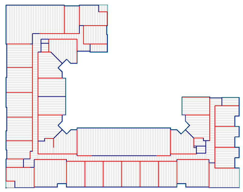
Here is a screenshot of the general layout of my building for reference. The red walls are the shear wall locations, blue walls are just gravity. Overall dimensions are about 213'x272'.

Screenshot_2022-10-12_111527_kmzocv.png
 
Whew that looks like a bit of work. If all your shear walls stack, it shouldn't be too much effort to get the forces from the Flexible diaphragm approach as well. I suppose You will have to make some assumptions about how the open fronts are behaving. That top left hand corner looks like it will cause you a lot of problems. Same with that big (laterally) open area in the central part of the floor.

Three sided diaphragms are not inherently unstable, there is a procedure to analyze and design them using flexible diaphragm assumptions. Its not an easy task to apply that approach to this arrangement.

Best of luck here, I would be interested in your results. You're going to be pushing that diaphragm pretty hard in some areas, and you have a ton of offsets in your shear walls so be careful about your detailing for drag/strut and such.
 
Yeah... thanks for the awesome building layout Mr. Architect lol

I am ultimately trying to figure out where I need drags/collectors and such. Most multifamily projects I have done in the past just have one central corridor that doesn't change directions, so at least the parallel shearwalls are similar in length to each other. This one is much more complicated.

Are you aware of any other software that analyzes wood diaphragms any better than RISA-floor/3D? Seems like there is a huge disconnect between software and the NDS/SDPWS.
 
I don't believe there exists any software that can accurately analyze any diaphragm. These are normally done by hand. You would need chords/drags at re-entrant corners and discontinuous chords. Terry Malone has a great publication on this. Link

I would start by laying out your individual diaphragms for the project. Then I would look at do you have a complete load path for chords, if nor add drags/chord ties. You will also need to account for drags around penetrations in the diaphragm such as stairwells or elevator shafts.

As for these unique shapes, these are becoming more and more common, at any given time we have up to 10 of these apartments under design, each one with similar shapes to what you show, but also different in many aspects, some much more complex in shape, picture elongated 7 sided members with varying angles of walls. There is no lack of "art" in these designs...
 
Agreed with Aesur I have not seen a diaphragm analysis software that is capable of doing design. The closest thing is to model the stiffness like your trying to. That leaves diaphragm shears, collectors, and chords as a post-processing step. This process can be tedious and give strange results so again I would try to have the rigid, and flexible forces in the back of my pocket for sanity checks and envelopes if needed.
 
Status
Not open for further replies.

Part and Inventory Search

Sponsor