Continue to Site

Eng-Tips is the largest engineering community on the Internet

Intelligent Work Forums for Engineering Professionals

  • Congratulations KootK on being selected by the Eng-Tips community for having the most helpful posts in the forums last week. Way to Go!

Self Priming centrifugal pump piping

Rymack

Mechanical
Nov 3, 2024
6
Good Afternoon, first post here looking for help designing a pump skid. Customer requires a skid with two self priming centrifugal pumps (one on standby). Pumps will be mounted on the deck of a barge and pumping out of four tanks below through a common header. Pumps were sized accordingly from the manufacturer to satisfy the suction lift, flow rates etc. My question is with the suction of the pump being 4” and the suction piping in the tanks being 4” how should the suction header be sized to avoid pumps getting cavitation? Also any information regarding piping layout would be appreciated as far as rules on the suction side of centrifugal pumps as far as pipe diameters of straight piping ETC.


Thanks in Advance
 
Last edited:
Replies continue below

Recommended for you

Since the tanks are located below the pump, the pumps are operating under a suction lift.

For this, the suction piping should be laid out with a continual rise toward the pump, avoiding high spots in the line to prevent the
formation of air pockets.

The header should also be located so that no air pockets can form.

The sizing of the suction pipe should ensure the availability of NPSHR at pump suction.
 
Reduce headlosses in the suction piping as much as possible. Its normal for suction piping to have a larger diameter than the discharge piping in order to reduce headloss. The diameter should be selected based on maintaining an acceptable velocity -- don't provide a 4" dia header just because the supplier is furnishing a 4" connection. Minimize the length of the header and avoid creating bends. If there is a bend, evaluate if a long radius fitting would be advantageous. Consider using full port valves. As others have said, check that you're meeting NPSH_r and are within the suction lift capability of the pump.
 
Last edited:
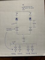
Here’s a rough sketch and a bit more information below. FYI This information has been given to the pump supplier for sizing the correct pump. See below a bit more info on the piping arrangement, any insight on this system would be appreciated

Suction lift - 4.5M

Suction piping - 4” NPS roughly 25’ of piping inside of the tanks below the pump (some horizontal runs, still 4.5m lift)

Discharge - 140-150GPM with another 6m of rise max when tide is low (plant it’s feeding is on shore) Discharge is running through a 130m 4” CPVC pipeline

All piping will be 4” XH, valves will be full port ball valves, all fitting will be of long radius.

Thanks in Advance
 

Attachments

  • IMG_0341.jpeg
    IMG_0341.jpeg
    1.8 MB · Views: 28
You might be able to save yourself a valve and some tees / elbows if you just stab the two pump inlets into the header, which I would make min 6" diam if its fairly close to the pumps.

You might get a little bit of preferential tank emptying, but it will or should be pretty close.

just make sure your valves and all the piping is suitable for full vacuum to avoid air ingress. Sometimes valves are set up to stop fluid coming out, not air going in...

Lift of 4.5m ( min liquid level in the tank to CL of the pump?) is decent, but don't expect much more.

Are there foot valves on the end of the pipes in the tank?

Otherwise looks good to me.


Thanks for the reply,

-Yes, 4.5M is from minimum liquid level to CL of pump (pump supplier has this information as well)
-Yes, We are going to install foot valves inside of the tank piping
-If i keep the arrangement as drawn would you still recommend upsizing the header? Or keep it all 4"
-I have sent out confirmation to the valve supplier about being suitable for full vacuum

Thanks
 
Last edited:
Observations:

1. Single strainer for 2 pumps-unless it is a dual strainer with facility for on-line cleaning, both the pumps need to shut-down for strainer cleaning. However, this may be OK if the water(or liquid) is clean and the cleaning can be done during maintenance shutdowns.

2. Foot valve used for priming: there could be problem of leakage (may be due to dirt sticking to flap) and hence loss of priming.

3. Check with pump supplier regarding NPSHR. Additional margin over NPSHR needs to be provided over the NPSHR as indicated by supplier to take care of design uncertainties etc. You need to perform NPSHA calculation and see what margins are available. The max. pressure drop across the strainer is also critical. If after the above calculation you find it is too tight for comfort, the following may be done:

a) increase the header as well as suction line sizes to 6 in
b) use 45 deg WYEs instead of tees.
 
Suction piping - 4” NPS roughly 25’ of piping inside of the tanks below the pump (some horizontal runs, still 4.5m lift)
Discharge - 140-150GPM with another 6m of rise max when tide is low (plant it’s feeding is on shore) Discharge is running through a 130m 4” CPVC pipeline

Is pump capacity controlled?
What exactly do you mean "self-priming"? Can you describe?
How are you going to fill suction piping with liquid for self-priming?
Why do you need a booth valve? Can you describe?
Does this liquid contain any amount of a dissolved gas?
What is suction intake design? Can you describe?
150gpm@4" = 4.3fps which is far above recommended velocity for suction piping. There is the risk this can lead to problems.
 
Last edited:
Was that thing a strainer in the single line??

Get rid of it. You don't have the head to allow it.

You will need min 1m and pref 2m above NPSHR to avoid cavitation.

Any reason why you didn't go for submersible or long shatf pump in each tank?
 
Thanks everyone for you input. FYI i'm a pipefitter who was approached for this install and I did not like the layout, thats why i reached out to get input from people with experience. See below my answers to questions above and I would love some more input from you all. Just trying to help the customer ensure this system will work .

-I will remove the strainer as the pump spec'd is good for solids and they have another filter before washwater enters the tanks
-customer does not want any equipment inside of the tanks, hence why we aren't going submersible or deep well pumps
-the pump will be capacity controlled on a float system (outside contractor)
-the liquid will not contain any dissolved gas
-suction piping arrangement will be a manifold on suction side of pump, and drop into the tanks of the barge, account for 25' of pipe in each tank (4.5M vertical from low level in tank to CL of pump) and four long radius 90s on each of the 4 runs inside of the tanks


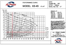
-see below pump curves and models of pumps from a couple different manufacturers (all info given to pump supplier)

any more input would be greatly appreciated!
 

Attachments

  • XS-4S 150GPM@30FTHD.jpg
    XS-4S 150GPM@30FTHD.jpg
    285.2 KB · Views: 9
  • KST3 Performance Curve.pdf
    197.2 KB · Views: 5
1/ Is this pump properly vented? I do not see any vent valve on P&ID you have shared. Where is the air going to go to?
INSTALLATION, OPERATION & MAINTENANCE MANUAL with PARTS LIST XS-S Series
Bypass Lines
Self-priming pumps are not air compressors. During the priming cycle, air from the suctionline must be vented to atmosphere on the discharge side. If the discharge line is open, and a check valve has been installed in the discharge line, the discharge side of the pump must be opened to atmospheric pressure through a bypass line installed between the pump discharge an the check valve. A selfpriming centrifugal pump will not prime if there is sufficient static liquid head to hold the discharge check valve closed.
...
In HIGH discharge head applications (more than 30 feet), an excessive amount of liquid may be bypassed and forced back to the wet well under the full working pressure of the pump; this will reduce overall pumping efficiency. Therefore, it is recommended that a All PrimeAutomatic Air Release Valve be installed in the bypass line. All Prime Automatic Air Release Valves are reliable, and require minimum maintenance. See AUTOMATIC AIR RELEASE VALVE in this section for installation and theory of operation of the Automatic Air Release Valve.
2/ Delete strainer. You have no enough NPSH for such features. If this type of pumps can't tolerate the liquid you are going to pump out you should get back to submersible pumps.
3/ Add shutoff valve on discharge of every pump. Check valve is not a shutoff one and is not able to assure the tightness of any level.
4/ Make sure the check valves are necessary in your design. Revome those if will find no a reason for installing those.
5/ Increase suction piping ID up to 1.5-2.0 fps. Make sure suction line has no gas pockets and is inclined to pump nozzle so way bubles are unable to accumulate.
6/ Describe the liquids this station is intended to pump out. Without this info forummembers are not able to help with NPSH margine which is still the critical point for this installation.
7/ Check the intake design with ANSI/HI 9.8. I am sure you are not familiar with the vortice phenomena. Otherwise actual achieved min liquid level in the barge will be surprisingly much higher than that expected and the "dead" volume resulted will call into question the pump station itself.
8/ Note that your suction piping operates under vacuum. This means a negligble vacuum leak can make the pump unable to selfprime. The P&ID you have shared has plenty of those potentially.
 
Last edited:
Thanks again for more information and input. See my answers below and feel free to fire back more


1. The pump has an auto air release valve built into it

2. Strainer is deleted

3. There will be a valve on discharge side of pump piping

4. I will revisit with client about check valves, if they seem redundant we can remove them

5. If we went to 5” STD pipe for suctions we would get to 2.4fps. Better? I can follow up and see if they are interested in 6” for a better system

6. Liquid will be washwater/rainwater collection from drydocks. Mostly water with small debris, grit, paint chips.

8.piping arrangement can be cleaned up to minimize bolted connections.

Thanks
 
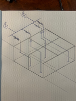
Do you have a drawing or sketch of the pipe end inside the tanks? This will be important if the min level is less than 1 to 2m above the pipe inlet

Is this intended to empty all the tanks at the same time or one at a time?

Emptying all at the same time will have different levels in the tanks without some trimming capability to even out differences in level.
 
Here is a very rough sketch of the tank layout, Feed into the tanks will just be stubbed into tank top 6" long being supplied from another pump source. vertical suction from the end of the suction pipe in the tank to CL of the pump will be 4.5M. Tanks will empty close to the same time as they will have crossover piping through the bulkheads to maintain the same level. Floats will be able to control heigh of water above suction pipe. Safe to account for 25' of pipe run into each tank with 3-4 long radius 90s. (i know its not ideal). total water in the barge will be 250,000 gallons and the water treatment plant its feeding has a 3000 gallon storage tank that feeds the system at 90 gallons a minute. The barge will never get pumped down very low as its just bulk storage of washwater from the dock.
 

Attachments

  • Barge Tanks rough .png
    Barge Tanks rough .png
    431.6 KB · Views: 7
1/ Assumed suction ID is 6", hydraulic pressure drop @150gpm is 0.5m - see file attached.
You can reiterate results by yourself - https://www.pressure-drop.online/
2/ Assumed water temp is 120°F water vapor pressure is 1.2m
3/ Atm pressure head is 10.5m
4/ Suction velocity head is negligble - assume 0m
5/ ELevation difference between impeller centrline and min water level is 4.5m (as per Rymack's post above)
6/ NPSH margin as per ANSI/HI 9.6.1 is 1.0m
7/ NPSHA = 10.5 - 0.5 - 1.2 - 0 - 1.0 - 4.0 = 3.3 m
8/ NPSHR as per manufacturer's curve is 2.0m
9/ Conlculsions: 3.3>2.0 that means you have ~1.6 times safety margin. Note that the calc above is not valid if the pump capacity is actually uncontrolled.

The pump has an auto air release valve built into it
Where is it routed to? Did you see figures in a manufacturer's manual?
image.png


vertical suction from the end of the suction pipe in the tank to CL of the pump will be 4.5M
The pump is not able to pump out up to end of suction line. And the actuall elevation difference can be much lower than that expected.
Note that my calc above is not valid as I assumed that min water level will be = elevation of the end of suction line. This is not true and you and your client should understand that point the sooner the better. Suction intake design is still critical for this barge.

If we went to 5” STD pipe for suctions we would get to 2.4fps. Better?
Let's find out together.
1/ Velocity is (6"/5")^2 = 1.44 times higher
2/ Hydraulic losses are 1.44^2 = 2.1 times higher
3/ Hydraulic pressure drop @150gpm is 2.1*0.5 = 1.0m
4/ NPSHA is 3.3+0.5-1.0 = 2.8m
5/ NPSH safety margine is 2.8/2 = 1.4 times
It is up to you to compare pros and cons of these 2 options (5" vs 6") and to decide which one is preferred.

Note that the water/wastewater contains significant amount of air and this air cause cavitation of the pump classical design of. In theory in your case this air can cause loosing of priming - see the paper attached for some references.

Note that the floating debris sucked in is unable to float down and therefore it will accumulate in the pump's vacuum chamber and hinder venting. My experience with operating of the similar pump installation is that this debris is the real pain as constantly causes loosing of priming. This is why a booth screen busket or a suction strainer is desired. And undesired as has been mentioned above by forummembers.

Note that the ordinary water can be explosive, as some examples see videos of flying watertanks
 

Attachments

  • Appication Guidelines for Pumping Liquids with Dissolved Gas.pdf
    4.6 MB · Views: 5
  • TGFTI's hydraulic study.xlsx
    13.4 KB · Views: 5
Last edited:

Part and Inventory Search

Sponsor