Continue to Site

Eng-Tips is the largest engineering community on the Internet

Intelligent Work Forums for Engineering Professionals

  • Congratulations cowski on being selected by the Eng-Tips community for having the most helpful posts in the forums last week. Way to Go!

Seismic Questions - Again 3

Status
Not open for further replies.

Althalus

Structural
Jan 21, 2003
152
Thank you to all who have helped me understand various provisions of Ch 11 and 12 of ASCE 7.

I have several things that I've interpreted, but I'm afraid I may be in trouble if I've interpreted incorrectly. I'm wondering if someone can clarify these for me.

ASCE 7-16 references follow:

1) Table 12.2-1 Type H (steel not specifically detailed for seismic...) can be used in lieu of C.4 (OMF) with only a slight increase in seismic coefficient Cs. Type H references section 14.1 for detailing requirements.
ASCE 7 said:
(Type H) shall be permitted for systems designed and detailed in accordance with AISC 360 and need not be designed and detailed in accordance with AISC 341
If we don't need to abide by 341, then why is it addressed in part 3 of 341-12 (cordovan colored)? I noticed that it disappeared from 341-16 (blue-grey version).

The big gaping hole (unless I've simply missed it) is that I don't see anywhere in ASCE where overstrength is required. It only states "where overstrength is required, use this method." Then it depends on ACI and AISC to instruct us on where to use it.

So, if 341 (which instructs us on when, where, and how to use Ω) is omitted in the design of a steel structure, how do I know when/where to apply it? We know from 341 that we need to apply it to connections for certain methods as outlined. But that entire book is ignored now. And I can't seem to find it in ASCE.

I also notice in 341-12 (R=3 section) does not mention Ω0 at all. It is simply a straigh-forward calculation even for the beam to column connection example.

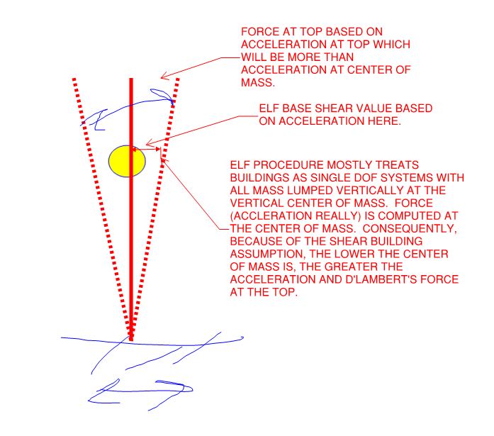
2) Can someone explain to me the reasoning / theory behind the vertical load distribution? re: Eq 12.8-11 & 12.8-12? I've performed a dummy calculation. A two story building with equal heights per story. Equal loads per story. About 2/3 of the seismic load is applied to the roof and 1/3 to the 2nd floor. This changes with different values of k. But how is it that the load from the second floor is now distributed to the roof level?

My line of thinking is that a building over-all is a cantilever. And if we think of a cantilever beam, there is no way that loading the middle of the beam will cause more shear at the free end of a beam. Shear would only effect the beam from the point of load to the fixed end. Yet with seismic, the load in the middle of a cantilever effects the shear at the free end of the beam?

What am I missing?
 
Replies continue below

Recommended for you

I'm no seismic expert, but I'll take a stab at your questions since I live in R=3 most of the time:

1) AISC 341 is all about seismic detailing. That is, detailing/design methods intended to ensure a ductile response during a seismic event. You don't want your connections or your columns failing before beams, for example. So even an OMF has some basic seismic voodoo mixed in forcing you to design certain elements for the expected strength rather than minimum, etc. R=3 or steel not specifically designed for seismic resistance, on the other hand, is just that - steel not specifically designed for it. So you design for the expected seismic loads, and that's about it.

As for why it's addressed in 341...just to give you an example, I suppose. As you mentioned, it's a very straightforward calculation. It's a method that can be used to resist seismic loads, so they put an example in the book. If you'll notice, it doesn't really tell you anything that 360 doesn't. Like with the SCM, the SDM has examples/guides in the front, and the specification (the actual 341) in the back. If you flip back to the spec (I think the tab is labeled "PROV" for "Provisions"...I can't seem to find mine at the moment), I don't think you'll find anything on R=3...it's just in the example tabs at the front.

Overstrength is mentioned in ASCE several times - things like diaphragm connections, etc. Search the forum...several people have listed out all the locations where it's found. If you have a PDF copy of ASCE 7, you can do a word search.

2) Seismic loading isn't actually a load applied to the building. It's a forced displacement. The foundation moves laterally and/or vertically, and the rest of the building goes along for the ride. To simplify the calculations we have the Equivalent lateral force method. So we approximate loading that would result in a comparable deflected shape. Rather than think of it as something pushing on the building, think of cracking a bull whip. Your hand doesn't move much, but relatively speaking the further out on the whip you go, the more drastic the movement. Same with a building. The earth moves a little at the foundation, but the top of a 15 story building sways a lot by comparison. So a lot of the "equivalent" force is allocated to the top and it decreases as you go down.
 
OP said:
My line of thinking is that a building over-all is a cantilever.

It is a cantilever but, by and large, the ELF procedure assumes that it is a cantilever dominated by shear deformation. So attempts to draw analogies with normal cantilevers dominated by flexural deformation can be problematic.

OP said:
But how is it that the load from the second floor is now distributed to the roof level?

It's not, although that is a very common misconception. Lowering the center of mass of the building results in an amplification of the acceleration at the top of the building and, therefore, the D'Lambert's forces there. It's best to think of this in terms of acceleration as shown below, rather than forces.

C01_ky8u7c.jpg
 
OP said:
The big gaping hole (unless I've simply missed it) is that I don't see anywhere in ASCE where overstrength is required. It only states "where overstrength is required, use this method." Then it depends on ACI and AISC to instruct us on where to use it.

I share your confusion & frustration with that. I currently view R=3 as the seismic system which I understand the least. Because R=3 rather than R=1 (hopeful elastic), there must be damage and energy dissipation somewhere. But where is that? Is it the same hot spots that would afflict an special or intermediate system? Is it air damping as the thing shifts around? Is it the generic shifting of drywall nails and window frames all throughout the structure? I suspect the last one but I should would like to see that in print someplace.

I've actually asked this twice now during seismic webinars hosted by some seismic heavy hitters. And, so far, nothing that I'd consider a real answer has come of the asking. Like me, they have a great understanding of R=8 systems with capacity design and either little knowledge of -- or little interest in -- R=3.
 
phamENG said:
If you flip back to the spec (I think the tab is labeled "PROV" for "Provisions"...I can't seem to find mine at the moment)

I don't see anything labeled "Provisions". There's "General Design Considerations" and "Analysis".

phamENG said:
Overstrength is mentioned in ASCE several times - things like diaphragm connections, etc. Search the forum...several people have listed out all the locations where it's found. If you have a PDF copy of ASCE 7, you can do a word search.

Thank you for your response.

I've done all those. It isn't there. I'm looking at ASCE 7-16 (word search "overstrength") and it doesn't say to use it anywhere for a steel moment frame without any diaphragms or collectors.

Every mention I can find is for:
[ul]
[li]Diaphragms & Collectors[/li]
[li]Tsunami effects[/li]
[li]Foundations of various types, incl anchors[/li]
[li]Discontinuous Walls...[/li]
[li]Tanks and vessels[/li]
[/ul]
The remaining search results are in the commentary. I didn't look through that very far. It seemed to just repeat everything in the body of the code.

It simply does not mention connections in ASCE (per a word search for "overstrength"). And if that is the case, then why is it listed in Table 12.2-1? The fact that is is listed should imply that we're supposed to apply it SOMEwhere. I just can't see where.

The one place I can think of where it MAY apply is the baseplate where the anchors go. I could see that. Then that famous article from Structure Magazine indicates that the anchors only need an Omega = 2.0 for R>3. But since this is R=3, then do we NOT apply Omega to the anchors? Anchorage has changed in the past few editions of ACI 318. Now they don't ask for any special requirements for SDC B on anchorage. They do, however state that the load combinations require E. But it doesn't comment on whether this is Eh or Emh. And it certainly doesn't say anything about Omega.

But the primary question I have is: If I design the beam to column connections in a moment frame without increasing the load by Omega-0, will I be in big trouble? Or is this typical?

You present a unique opportunity. You say you "live in R=3". Do you do it for steel moment frames? Where to YOU apply it for a steel moment frame using R=3 without any diaphragms/collectors or wall discontinuities? And, out of curiosity, how about for Braced frames?
 

OK, I get the whip idea. I suppose that makes sense. But that brings up another question...

1. For a single story building, do I then apply the entire weight of the building at the roof (as an "equivalent" load)? I would think that half of the walls and columns would go to the floor (provided that the load path would normally distribute that way).

2. For a two story building, the w1 would be applied at the 2nd floor and the w2 would be applied at the roof? No consideration for applying anything at the wall levels? That is what the equations seem to be saying. But I would really appreciate a more experienced person verifying this.

Thanks.
 
By saying I live in R=3, I mean I live in a very low seismic area. With the exception of a couple federal jobs in California that were D, a hospital support building a couple hours away that barely tipped into C, and work in a graduate level Seismic Steel design course, everything I design is SDC B. We also have hurricanes here, so with R=3, the seismic base shear is typically way less than half of the design, horizontal wind load. The only exceptions I can think of are the long, skinny hotels - lateral load parallel to the long face tends to become seismically dominated because the free wind area is really small but the participating mass for ELF calcs doesn't change.

For overstrength - yep, that's about it. I still can't put my hands on my SDM...it's in a box around here somewhere...but if you're using steel not specifically designed for seismic, those items you found are about it. Unless one of the other material codes puts you into it, you don't need to use it. If you're in SDC B, you essentially don't need to use it except at the foundation in a few cases. SDC C still permits R=3, and there are more requirements for diaphragms and collectors, etc. So places where this method is allowed with essentially no overstrength consideration are limited to places where people only understand earthquakes in an abstract sense. We get a little tremor about once a generation or two. We had one about 6 years ago (maybe longer now? I was out of town when it happened)...the Washington Monument's elevator broke, a couple gargoyles fell off of the National Cathedral, and one or two houses near the epicenter shifted a few inches - it seems we only learned about anchor bolts on the east coast in the late 90's (not a joke - my house sits on beams resting on a series of CMU piers with no positive anchorage at all). Was it a "design level" quake? No. But I also didn't hear of any damage reported to steel frame buildings at all. At design level, you'd still have lots of damage but (ideally) no catastrophic collapse. A steel frame, even with R=3, has some ability to absorb that energy through inelastic deformation. The seismic and statistics gurus who decide such things determined that without detailing for it, a frame that meets the requirements of 360 alone can absorb enough to reduce the ELF by a factor 1/3.

No, I do not use overstrength on moment frames when using R=3. Though I will admit I haven't but a tremendous amount of thought into it - as I said before, wind loads around here are often 2 to 4 times the seismic load, depending on the weight of the building. So I sort of have a built in overstrength there when you compare the loads I'm designing the frame for compared to the seismic load.

Regarding vertical distribution, you could probably get away with splitting it and putting the weight of the roof and upper half of the walls and parapets on the roof level and the rest at the ground...but I don't. It's more conservative to put it into the roof and doesn't usually change things too much. If the design starts getting out of hand, I'll back off, but if I get a reasonable design considering all the weight assigned to the roof diaphragm I'll do it. For multistory, I break the mass halfway between the diaphragms. The walls have their own anchorage requirements independent of load calculations for the seismic force resisting system.
 
phamENG said:
No, I do not use overstrength on moment frames when using R=3. Though I will admit I haven't but a tremendous amount of thought into it - as I said before, wind loads around here are often 2 to 4 times the seismic load, depending on the weight of the building. So I sort of have a built in overstrength there when you compare the loads I'm designing the frame for compared to the seismic load.

Thanks again for your post.

I have just one more redundant question for you. In SDC B, R=3 method, do you apply Omega to the anchors? ACI simply doesn't mention it in 318. It doesn't seem to say much at all about anchors in SDC B other than
[ul]
[li]Alternate methods may be used.[/li]
[li]Use the requirements in the section.[/li]
[/ul]

But the requirements only say that E must be included in the Load Combinations. It does not specify Eh vs. Emh.

FOR BACKGROUND: I'm preparing a "generic" report for a pre-fab building product with specific variables. It is supposed to be 120 mph wind and SDC B (with the highest variables for SDC B). Obviously, in reality, S1 and Ss are such that they never max out at the same time. But that is what I'm working with. And I've got a HEAVY steel building where the Eh = 455 kip; W = 95 kip. So, yeah, seismic controls here. Wind will only control components and cladding -- much lighter with large sail area.
 
No, I don't. Though you do have an interesting situation. It may be prudent to do so - or at least design the anchors such that your most likely failure mode is ductile (steel failure). But I don't believe there's anything in the code saying you have to.
 
Eng . Althalus (Structural),
I read the thread and screened your other posts.. Pls find below my responds to some of your questions ;

- The SFRS H is for ;STEEL SYSTEMS NOT SPECIFICALLY DETAILED FOR SEISMIC RESISTANCE and applicable for SDC B and SDC C.
Copy and paste of 14.1.2.2.1 Seismic Design Categories B and C;


(... steel structures assigned to Seismic Design Category B or C shall be of any construction permitted by the applicable reference documents in Section 14.1.1. Where a response modification coefficient,R, in accordance with Table 12.2-1 is used for the design of structural steel structures assigned to Seismic Design Category B or C, the structures shall be designed and detailed in accordance with the requirements of AISC 341.
EXCEPTION: The response modification coefficient, R,designated for “steel systems not specifically detailed for seismic
resistance, excluding cantilever column systems” in Table 12.2-1 shall be permitted for systems designed and detailed in accordance
with AISC 360 and need not be designed and detailed in accordance with AISC 341.

Copy and paste of C 14.1.2.2.1 (...........The first option is to design the structure to meet the design and detailing requirements in AISC 341 (2016) for structures assigned to higher SDCs, with the corresponding seismic design parameters (R, Ω0, and Cd). The second option, presented in the exception, is to use an R factor of 3 (resulting in an increased base shear), an Ω0 of 3, and a Cd value of 3 but without the specific seismic design and detailing required in AISC 341 (2016). The basic concept underlying this option is that design for a higher base shear force results in essentially elastic response that compensates for the limited ductility of the members and connections.)..

So IMO, the designer is free to choose Part C Steel ordinary moment frames or Part H .. If you think the use of R = 3 is more economical, you may prefer part H to be the exempted of AISC 341 detailing costs.


- Regarding the reasoning ,theory behind the vertical load distribution? re: Eq 12.8-11 & 12.8-12 12.8.3 Vertical Distribution of Seismic Forces.;

Refer to FEMA 750 ; (....C12.8.3 Vertical Distribution of Seismic Force The deformed shape of the structure of Figure C12.8-3 is a function of the exponent k, which is related to the fundamental period of vibration of the structure. The variation of k with T is illustrated in Figure C12.8-4. The exponent k is intended to approximate the effect of higher modes, which are generally more dominant in structures with a longer fundamental period of vibration....)

basis_of_eq._12.8-12_vppbsr.jpg


- Regarding the Seismic wt calculation , you may follow the following steps,

i- Own weight of a floor and LL's are considered at that floor level,
ii- Own wt of columns and walls in a storey height is distributed equally between lower and upper floors,
iii- The seismic masses are lumped as a single point at the relevant storey..


I hope my respond answers to some of your questions.. Could be tomorrow , i may write for the use of OVERSTRENGTH factor Ωo..
 
For walls, I believe it common practice to distribute their contributions to both the levels above and the levels below. That's always what I've done. More detailed seismic treatment of the walls themselves mostly comes into play in the design of the attachments between the facade and the framing levels.

Althalus said:
Obviously, in reality, S1 and Ss are such that they never max out at the same time.

I don't believe that its implied that S1 & Ss would max out at the same time. Rather:

a) The two parameters are used as metrics to help generate the response spectrum curve that allows you to estimate acceleration based on your particular structure period and;

b) Ss is applied to special things that do not benefit from the flexibility of the global structural system and may, in fact, have a relatively short period.
 
Status
Not open for further replies.

Part and Inventory Search

Sponsor