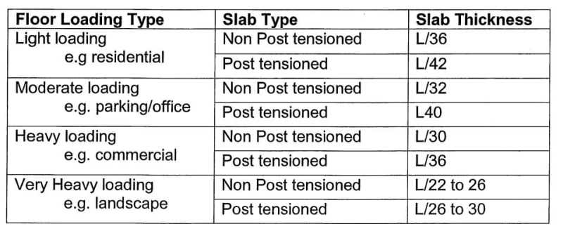
I have this 4m cantilever flat slab that has 35mm long term deflection using normal non-PT RC slab analysis. I just wanna know if there is any way that I can estimate the deflection of a PT one based on the normal RC model that I have built? (doesn't need to be accurate, just wanna know how much deflection roughly PT can save). I am not familiar with PT slab and it will be designed by others. Right now I just wanna estimate the thickness without establishing a detailed model with tendons in so I can keep going with my structure. Thank you.
Tek-Tips is the largest IT community on the Internet today!
Members share and learn making Tek-Tips Forums the best source of peer-reviewed technical information on the Internet!
-
Congratulations MintJulep on being selected by the Eng-Tips community for having the most helpful posts in the forums last week. Way to Go!
Rule of thumb for PT slab deflection?
- Thread starter dis_
- Start date
Similar threads
- Locked
- Question