Glenn Gordon
Mechanical
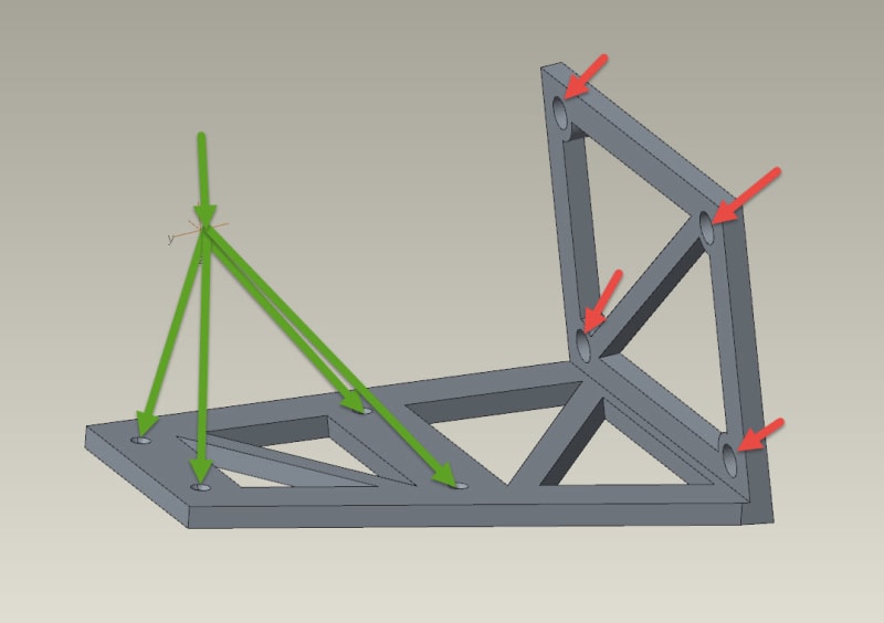
Basic setup - Creo Simulate at PART level.
Material Properties assigned.
Red Arrows = Four large holes are where the part is constrained
Green arrow(s) = Load acting straight down upon a rigid link established between the chamfer surfaces of the four smaller holes.
Question = How do I apply a load (located at a point in space) upon the surfaces of a rigid link?
Thanks,
Glenn