Hi,
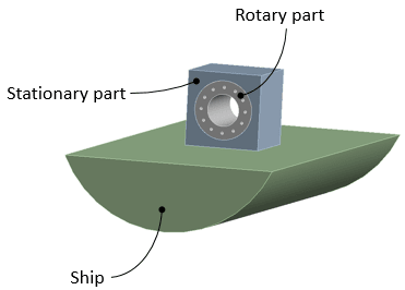
I'm trying to do a rigid dynamics simulation to investigate how some cargo react to ship motion during transport. I've created a simple model as seen below [Figure 1].

Figure 1: Model nomenclature
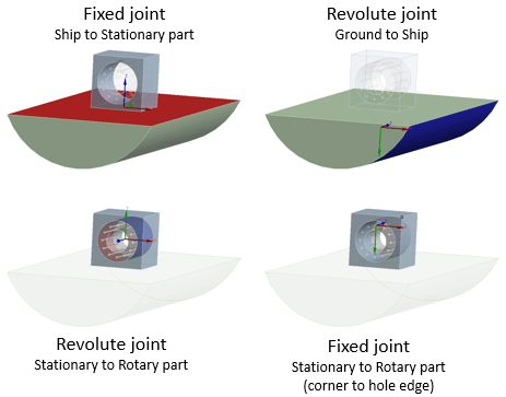
I have two parts that are connected with a bearing. The "blue" part (Stationary part) will be secured to the ship deck, and the "grey" part (Rotary part) will be able to rotate freely. Securing the Stationary part to the ship deck has been achieved by adding a fixed joint between the contacting faces of the Ship and Stationary part, and the free rotation by a revolute joint between the contacting faces of the Stationary and Rotary part [Figure 2, left].

Figure 2: Model joints
Only roll is considered to have any effect on the relative motion between the Stationary and Rotary part. A body-ground revolute joint has been added to the curved surface of the Ship [Figure 2, top right] used for application of the roll motion of the ship. The joint rotation applied can be seen in [Figure 3] below.

Figure 3: Joint - Rotation
When running this simulation it results in the Rotary part rotating relative to the Stationary part when the ship is rolling in one direction but having no relative motion between them, when rolling in the other. Resulting in the Rotary part rotating further and further away from it's original position. Intuitively, I would expect the Rotary part to be at it's initial position at the end of a roll cycle (under these idealized conditions). Is this behaviour as expected, or is there something in the model setup that is causing this behaviour?
The result I'm interested in is the force needed to keep the Rotary part from rotating relative to the Stationary part. To simulate a connection between these two parts, I've added a fixed joint between the corner of the Stationary part and one of the hole edges of the Rotary part. When I probe the force in this joint, it is constant, which is not what I would have expected either. Especially considering the movement seen during the simulation. Can this joint force be explain (from what I've told so far)?
I've also tried making a simulation only using the Rotary and Stationary parts, in which rotating the Stationary part about their "common" axis doesn't result in any motion of the Rotary part (but of course relative motion between the parts). However, when translating the Stationary part (in the plane normal to the "common" axis), there is relative motion between the two parts.
I'm hoping someone can help with this, so I will better understand this problem. I've never worked with rigid dynamics before, so this has purely been set up by doing what I found to be intuitive.
Thanks in advance.
I'm trying to do a rigid dynamics simulation to investigate how some cargo react to ship motion during transport. I've created a simple model as seen below [Figure 1].

Figure 1: Model nomenclature
I have two parts that are connected with a bearing. The "blue" part (Stationary part) will be secured to the ship deck, and the "grey" part (Rotary part) will be able to rotate freely. Securing the Stationary part to the ship deck has been achieved by adding a fixed joint between the contacting faces of the Ship and Stationary part, and the free rotation by a revolute joint between the contacting faces of the Stationary and Rotary part [Figure 2, left].

Figure 2: Model joints
Only roll is considered to have any effect on the relative motion between the Stationary and Rotary part. A body-ground revolute joint has been added to the curved surface of the Ship [Figure 2, top right] used for application of the roll motion of the ship. The joint rotation applied can be seen in [Figure 3] below.

Figure 3: Joint - Rotation
When running this simulation it results in the Rotary part rotating relative to the Stationary part when the ship is rolling in one direction but having no relative motion between them, when rolling in the other. Resulting in the Rotary part rotating further and further away from it's original position. Intuitively, I would expect the Rotary part to be at it's initial position at the end of a roll cycle (under these idealized conditions). Is this behaviour as expected, or is there something in the model setup that is causing this behaviour?
The result I'm interested in is the force needed to keep the Rotary part from rotating relative to the Stationary part. To simulate a connection between these two parts, I've added a fixed joint between the corner of the Stationary part and one of the hole edges of the Rotary part. When I probe the force in this joint, it is constant, which is not what I would have expected either. Especially considering the movement seen during the simulation. Can this joint force be explain (from what I've told so far)?
I've also tried making a simulation only using the Rotary and Stationary parts, in which rotating the Stationary part about their "common" axis doesn't result in any motion of the Rotary part (but of course relative motion between the parts). However, when translating the Stationary part (in the plane normal to the "common" axis), there is relative motion between the two parts.
I'm hoping someone can help with this, so I will better understand this problem. I've never worked with rigid dynamics before, so this has purely been set up by doing what I found to be intuitive.
Thanks in advance.
