Continue to Site

Eng-Tips is the largest engineering community on the Internet

Intelligent Work Forums for Engineering Professionals

  • Congratulations 3DDave on being selected by the Eng-Tips community for having the most helpful posts in the forums last week. Way to Go!

Retaining wall repair rec

MAEngr

Structural
Jul 28, 2021
10
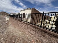
I am evaluating an exterior retaining wall that a contractor built to prescriptive codes. They came back after inspection and added two feet of additional retaining height which means insufficient rebar in the wall and inadequate footing sizes. The wall is starting to bow in the middle. The owner would like to not demo and rebuild the wall. My thoughts on repair would be to add a haunched wall butted against the existing wall with dowels and to add additional concrete/rebar to the footing. Is this the approach you all recommend? They would also be open to a buttress wall in the middle on the exposed side since that side is downhill and not visible. I don’t like this option as much.
 
Replies continue below

Recommended for you

Can you post a picture of the wall?
 
Sometimes walls are stabilized using lateral helical anchors.
 

Attachments

  • wall anchor.JPG
    wall anchor.JPG
    34.7 KB · Views: 30
Thanks both for the responses. This is currently preliminary. I will be going on site to evaluate the current conditions later in the week. A bit more clarification based on information provided to me which also changes how I want to proceed. It is an exterior prescriptive CMU retaining wall supporting a backyard patio deck above. The contractor added 2’ on top of the wall post inspection, so the existing block size is too small (8” instead of 12” per the table) and doesn’t match the specification for the corrected wall height, and the vertical rebars are also undersized now.

Based on the current conditions it seems like the helical anchors are the best bet. I was also looking into carbon fiber support, but I dont believe that will work here. Is this document a good source for calc’ing my anchor diameters and lengths?

Would adding a concrete wall/haunch to the exterior face of the cmu wall be out of the picture as another alternative solution?
 
Honestly, it would help to know a little more. Total length of wall, height of wall. And, pictures.

Another question is whether you believe the safety factors for sliding and overturning are sufficient.... It which case it's just an issue of reinforcement of the wall.

Concrete or masonry? If it's masonry, there could be a possibility of reinforcing through ungrouted cells.
 
The length of wall is 60'. Height varies from 4' to 8'-8". I have attached some images as well as a sketch of the detail I am proposing. I would appreciate any comments on any adjustments or items missing from the detail.

The factor of safety for sliding is 0.72 and overturning is 0.95 and the vertical bars are currently #4s at 8” o.c. so adding vertical bars only wont work. Since it is on a steep hillside I feel like increasing the footing size and adding a key would be troublesome. Calculation-wise if i added 2’ of footing to the toe and placed a 15”w x 21” deep key at the end of the toe i could get both overturning and sliding resolved, but then the top of footing would protrude above grade. With the key added it should put the footing penetration back below where it needs to be. Does this seem like a reasonable alternative?

If there is another proposed solution instead of the helical piles I am all ears.
 

Attachments

  • Helical pile detail.pdf
    155.5 KB · Views: 18
  • Photo (1).jpg
    Photo (1).jpg
    2.7 MB · Views: 66
  • Photo (2).jpg
    8.7 MB · Views: 4
  • Photo (3).jpg
    Photo (3).jpg
    4.1 MB · Views: 51
  • Photo (4).jpg
    Photo (4).jpg
    3.1 MB · Views: 47
  • Photo (5).jpg
    Photo (5).jpg
    3 MB · Views: 47
  • IMG_0455.png
    IMG_0455.png
    101.6 KB · Views: 53
  • Helical tieback @ CMU wall.PNG
    Helical tieback @ CMU wall.PNG
    109.5 KB · Views: 59
Last edited:
They would also be open to a buttress wall in the middle on the exposed side since that side is downhill and not visible. I don’t like this option as much.
Well, you shouldn't. If the wall is 60 ft long, I am not sure how you can justify one central buttress as being effective.
The factor of safety for sliding is 0.72 and overturning is 0.95 and the vertical bars are currently #4s at 8” o.c. so adding vertical bars only wont work. Since it is on a steep hillside I feel like increasing the footing size and adding a key would be troublesome. Calculation-wise if i added 2’ of footing to the toe and placed a 15”w x 21” deep key at the end of the toe i could get both overturning and sliding resolved, but then the top of footing would protrude above grade. With the key added it should put the footing penetration back below where it needs to be. Does this seem like a reasonable alternative?
Don't you still have a stem bending issue? Likely some footing bending issues as well. I think tie-backs or reasonably spaceed buttresses either in front of or behind the wall (if possible) are your best choices.
 
Is the existing footing as shown on your drawing of the tieback or is it more of a cantilever gravity retaining wall footing that extends farther under the fill than depicted?

If this is not your original design, shield yourself for the potential of the water that falls on the uphill side porous patio to migrate under the entire wall and slowly erode the material from under the wall. It tends to seek the closest place to discharge to. That is easy to happen with some fills and rain intensities. I do not know how wet it gets there, looks pretty much like desert, so it may not be a concern.

Are the existing #4s doweled into the footing or just in the block cells. Since the #4s are 8" oc, there must not be any hollow cells.

Right now for me, tiebacks look like the solution. I think your need to show a wide plate on the exterior of the wall or a horizontal channel where the tiebacks are. I think you have to make a hole large enough for the helix to pass through and that hole has to be sealed in the end. You need a way to spread out the tieback force or you may just get new cracks if not. I have never used a tieback on a block wall but have seen some post installation.
 
The original retaining wall was not my design. It was a city prescriptive design a contractor used and then built additional height on top of after inspection. They originally built to a 6' spec and then added up to 2.5' of backfill/pavers after inspection as a change order. There are weep holes at the base of the wall. It is in a desert, but rain does occur and the pavers up top can accumulate small ponding temporarily due to the poor construction craftsmanship.

In my detail I do have that Chance C1500121 bracket at the face of the wall and a hilti epoxy for once the pile is in place. Should there be an additional plate or c-channel I should add between the bracket and exterior face of the cmu wall? Is there a typical spec starting point you can recommend if so?
 

Attachments

  • 1749692389183.png
    1749692389183.png
    192.5 KB · Views: 21
I think you have to make a hole large enough for the helix to pass through and that hole has to be sealed in the end.
Around here, when possible, they will excavate a bit on the backfill side and push the tieback thru from the rear so they don't need a massive hole.
 
Around here, when possible, they will excavate a bit on the backfill side and push the tieback thru from the rear so they don't need a massive hole.
I have heard of this being done also. Better option if you can excavate on the uphill side. I saw how large of an area your drawing depicted being removed where the anchor was and assumed that your plan was to push helix through the wall.

Your anchor spacing tends to dictate if you need a whaler to spread out the point load. You are placing a high point load at one location intended to restrain several feet of wall that most likely does not have a lateral element present to help spread the force out at that location. It can spread vertical easier because of the rebar than it can laterally. Not sure if there is a bond beam on yours. The prescriptive detail only shows a bond beam closer to the bottom than the top.

As far as the water intrusion, I was more talking about water that percolates down several feet from the wall and can seep down lower than your weepholes. It still wants a way out and tends to migrate to open trenches and embankments when they are close by. Weepholes are for water control at the wall but may not intercept all the water several feet from the wall. More of a concern where I am because we get heavy rains, prolonged rains and a lot of times the soil can have a lot of sand mixed in it.
 
Thanks Ron. Could you point me in the direction of typical spec's and attachments to a CMU wall for a whaler?

The contractor may be open to excavate the uphill side which could help reduce the opening, but for now I gave the option of drilling through the wall and wanted to ensure the hole was big enough for the 12" helix. The wall was built using the detail on the left which shows the 8" bond beam at the top of the wall.
 
I don't have one but I have found Chance Anchors to be a very good source of information at times. They have sales reps in most areas and have generally been helpful for me. The franchise holder in the county I used to work was one of those helpful and knowledgeable unicorns.

I have never had to use a whaler except at an unsightly unfinished basement, so the appearance was a non-issue. I used a continuous 12" channel. The wall was hollow to start with, so it got grouted during the repair.

I did not notice the upper bond beam in the left detail, sometimes I lose focus, Hey look a squirrel just ran past my window with a banana peel.
 
Thanks Ron. I reached out and they are providing some insight.

Regarding your question "Is the existing footing as shown on your drawing of the tieback or is it more of a cantilever gravity retaining wall footing that extends farther under the fill than depicted?" (not sure how to respond to specific texts on eng tips) the bottom of footing is 2'-1" below grade, my detail doesnt quite match that graphically.

To me it seems like the tiebacks are the only viable solution besides tearing out and replacing the wall. If i did some buttress walls spaced every 10' they would be buried up to something like 12' below the existing footing just avoid sliding concerns on such a steep hillside. Any other thoughts? Someone proposed c-channels or w-flange beams on the exterior face but i dont see how that alone could work. I could treat it like cantilevered columns but the footing would be significantly undersized.
 
Regarding your question "Is the existing footing as shown on your drawing of the tieback or is it more of a cantilever gravity retaining wall footing that extends farther under the fill than depicted?" (not sure how to respond to specific texts on eng tips) the bottom of footing is 2'-1" below grade, my detail doesnt quite match that graphically.
I meant does it extend laterally underneath the backfill than depicted. Usually there is more footing making up the heel than the toe.
 
No, the prescriptive design has it as a 3' wide footing centered under the wall.
 
Another option I would like to propose to the contractor is to remove and replace the areas of the wall retaining more than 6' of soil and build it correctly. This would require a couple of control joints where they have to remove the inadequate wall. is the NCMA the best resource for this considering its an existing wall? I'd have him build it properly and then dowel the two walls together with the horizontal reinforcement of the new wall.
 
I'd vote for your last option...have them rip it out and do it correctly. I'd be concerned that the vertical rebar is not positioned exactly where it is supposed to be within the cores of the CMU. This will drastically change the flexural capacity of the stem. I've seen where they have it installed on the incorrect face. Have you been able to verify exactly how the wall was constructed, not just how it was supposed to be constructed?
 
I have the special inspection reports but they don’t specifically mention the rebar being on one face or the other. We haven’t done any destructive testing yet.
 
One other thought I had was to excavate 9 feet of soil behind the wall and replace with geofoam to help greatly reduce the stress on the wall. While the soil is excavated I would also have the contractor epoxy any cracking on the heel side of the wall. This seems like a viable solution to me that doesn’t involve tearing down the wall. Thoughts?
 

Part and Inventory Search

Sponsor