Continue to Site

Eng-Tips is the largest engineering community on the Internet

Intelligent Work Forums for Engineering Professionals

  • Congratulations 3DDave on being selected by the Eng-Tips community for having the most helpful posts in the forums last week. Way to Go!

Repairs to vertical CJ's between concrete columns and structural walls

Status
Not open for further replies.

Ingenuity

Structural
May 17, 2001
2,374
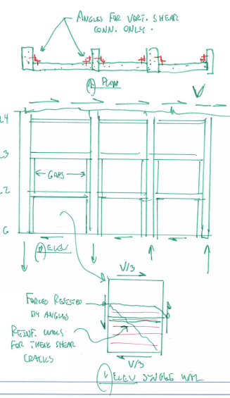
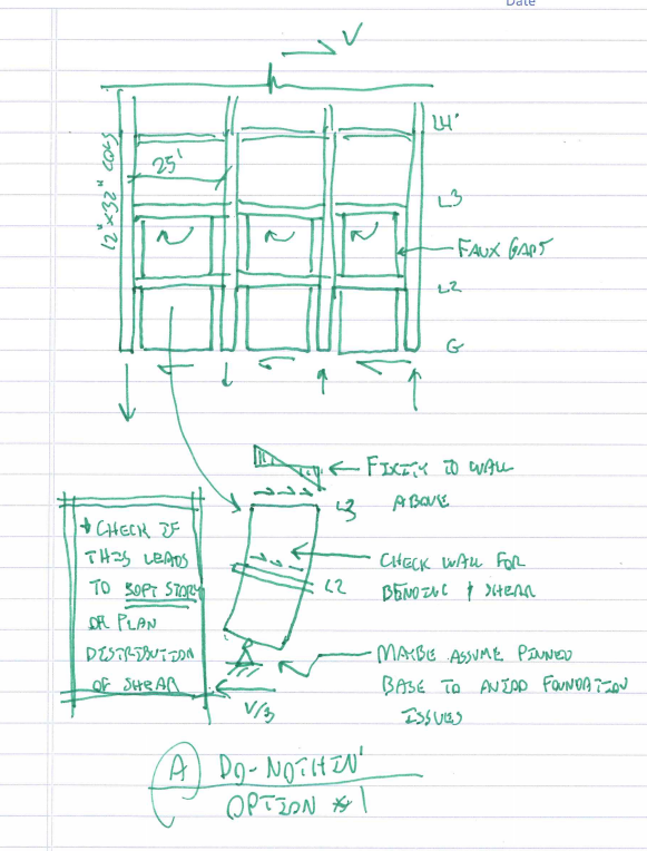
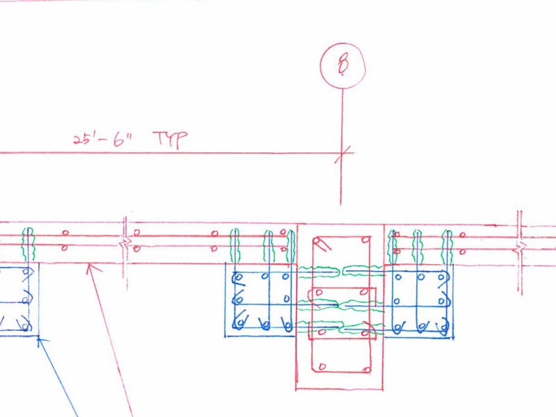
The general contractor to a 7-level concrete building consisting of 4 levels of residential and 3 levels of parking (all above ground) constructed the perimeter rectangular columns to the parking level using steel formwork, then after stripping the forms, constructed the concrete structural walls that are orthogonal to the long-axis of the column. 36"x12" columns with 8" walls that infill between the columns that are on 25' centers.

The contractor did not provide any horizontal reinforcement between the wall/column interface, nor was there any effort to roughen the off-form finish to the columns prior to constructing the walls.

The walls are part of the main lateral force-resisting system.

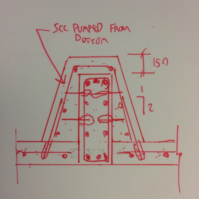
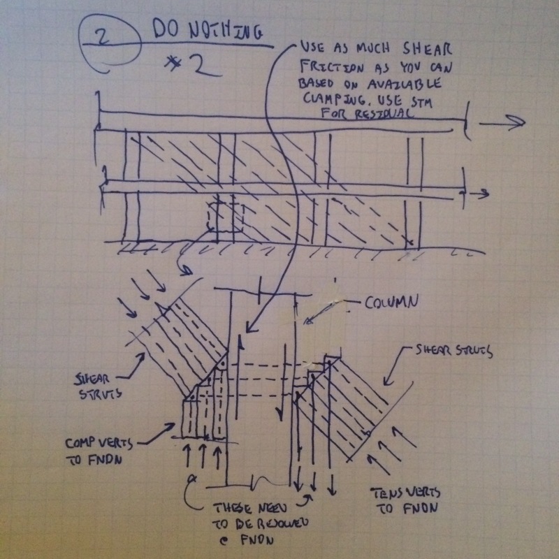
I have looked at more 'conventional' repair techniques like 1) drilling and dowelling in rebar and CIP concrete, and 2) horizontal steel through-bolts that pass though the columns 12" width and anchor to adjacent walls, with required fire protection.

I also looked at carbon FRP options to horizontally tie the adjacent walls through the columns, but without any mild steel rebar I am hesitant to rely upon a brittle materials like FRP, even if I downgrade the stress/strain levels.

Has anyone undertaken successful reinstatement of such a situation, and care to share their method/s?

Thank you.
 
Replies continue below

Recommended for you

I would usually post a sketch of the situation, however I am traveling right now so no access to posting a sketch.

I should have mentioned that there are 3 horizontal walls for a total wall length of 3x25', with 1 column at each end, and two intermediate columns that 'break-up' the continuous wall into effectively three segments.

The above is applicable over the 2 lower levels.
 

I can't say that I've done a repair on this kind of condition, but I'll offer the following thoughts:

I understand that the walls are part of your design MLFR system. Are there columns at each end of the wall that is intended to help resist forces parallel with the wall? If so, would not the wall perform as a 'strut' between the top of one column and the bottom of the opposing column? Vice versa for forces in the opposite direction.

Did the slab (and/or beams?) over-pour the wall? I would assume that it did, so you do have some connectivity (of sorts) between the tops (and bottoms) of the walls & columns. Perhaps an analysis of the as-built condition is worth examining.

While this is a sometimes common construction method, as one who has been involved it concrete construction for a few decades, I would almost always assume (that nasty word) that the concrete placement is intended to be monolithic, and any other approach requires the EoR's approval.

However, that said, I find that too often that the drawings (in plan) show closed lines around the columns and closed lines representing the wall(s). This can imply separate construction. Sometimes it's to the everyone's advantage to place the column independent of the walls and do the walls as infill between the columns. This can be advantageous with respect to the speed of construction and optimization of the formwork.

I don't ever recall seeing an explicit note or spec statement requiring that all walls touching columns be constructed as a monolithic placement. From my perspective it has always been assumed (!) that if they touch, it must be monolithic. Often with MLFR systems the EoR provides a plan detail showing the reinforcing layout, which then clearly establishes the requirement for a monolithic placement if the wall horizontal bars extend into the columns.

As for a real repair (i.e. tying the wall to the columns over their entire height), this would involve a lot of drilling and a high probability of nicking some of the column ties. You certainly cannot develop the strength of the horizontal bars with epoxied-in dowels alone. Perhaps you could use headed bars by drilling a larger diameter hole perhaps 3-4" (to accommodate the head + cover) into the opposite face of the column, then a smaller hole the rest of the way through and into the wall for the bar diameter. Not sure if this will develop better strength than just a plain straight dowel.


Ralph
Structures Consulting
Northeast USA
 
As I understand it, the construction drawings call for reinforcement between the walls and the columns and the contractor did not provide the necessary reinforcement. I'd say that drilling through the columns and epoxying in the necessary rebar is probably the simplest and cleanest way to go (If you need to go in at an angle, you will lose a little from the shear capacity but will make installation doable). Steel plates and FRP to the outside face seems ugly to me.

Do the walls need to be continuous? Separate walls will be more flexible and the shear transfer at the foundations will need to be reviewed, but if the detailing level is low enough... Who knows.
 
Do the walls and columns continue the full height of the building?

I like to debate structural engineering theory -- a lot. If I challenge you on something, know that I'm doing so because I respect your opinion enough to either change it or adopt it.
 
Obviously a "do nothing" approach should be explored if it has merit. I've no doubt that you've already considered and rejected that however.

I believe that you could get away with just a vertical, bolted angle shear connection between the walls and columns, similar to what might be done in a precast scenario.

Capture_vfh6bf.png


I like to debate structural engineering theory -- a lot. If I challenge you on something, know that I'm doing so because I respect your opinion enough to either change it or adopt it.
 

KootK - Based on the OP's description I do not believe there are gaps between the ends of the walls and the face of the columns. It sounds to me like the contractor simply cast the ends of the walls against the columns.


Ralph
Structures Consulting
Northeast USA
 
Regardless of gap or not, it's likely that Koot's proposed repair would be the easiest to design and quickest to install. In my books that generally means it's the best option, however there may be other constraints at play.
 
RHTPE said:
Based on the OP's description I do not believe there are gaps between the ends of the walls and the face of the columns. It sounds to me like the contractor simply cast the ends of the walls against the columns.

We're on the same page there Ralph. I drew the joints as gaps because, structurally and conceptually, that's how I see them. Essentially, joints incapable transferring vertical shear or horizontal forces across the joint.

I like to debate structural engineering theory -- a lot. If I challenge you on something, know that I'm doing so because I respect your opinion enough to either change it or adopt it.
 
If it's an exterior wall with some kind of treatment on the outside, one might be able to do something similar with flat plates that wouldn't be exposed to view.

I like to debate structural engineering theory -- a lot. If I challenge you on something, know that I'm doing so because I respect your opinion enough to either change it or adopt it.
 

KootK - I agree with you regarding the transfer of vertical shear. However, if the wall were cast directly against the face of the columns, would not the transfer of a horizontal (compressive) force be possible? Granted there would be a vertical component in the case of lateral building load, but the slab/beam above (or below) may be adequate to resist that vertical force component, combined with the vertical wall reinforcing extending from the wall into the beam/slab above & below. I guess this depends on the magnitude of shrinkage of the wall at the top that might open up a very small gap between the end of the wall and the face of the column. Even then, perhaps an epoxy crack repair method can remedy the shrinkage possibility.

I'm of the same mind that if the as-built condition works, is it really necessary to initiate any repair?

Referring to Teguci's comment, the OP did not state that the construction drawings called for reinforcing that would connect the walls to the columns. As I previously stated, I personally would have assumed (!) that the walls & columns would be a monolithic placement. Perhaps the approved rebar drawings correctly showed the EoR's intent, but the contractor ignored them. Again, I have seen many projects where the walls were constructed after completing the columns.

I will step onto the soap box one more time about the clarity of the contract documents. If the drawings imply separate placements and if there is no detail to the contrary, a contractor will approach the job in a manner that he/she feels is most economical and expedient. Wall forming with integral columns in the stated configuration are time consuming and difficult to assemble - the method chosen is certainly more expedient.


Ralph
Structures Consulting
Northeast USA
 
You could consider this a confined masonry shear wall with a very big masonry unit .

If there wasn't any reinforcing between the walls and columns on the CDs, then it is appropriate to consider these items separately. Shrinkage will place a control joint at these reentrant corners and shear friction = 0 without reinforcement. ACI (14.2.6) codifies this by requiring walls to be anchored to columns (ie the CDs should have shown this rebar continuing through the columns). In hindsight, the detailing of threaded splices would have done well to alleviate this problem.
 
RHTPE said:
However, if the wall were cast directly against the face of the columns, would not the transfer of a horizontal (compressive) force be possible?

My thoughts on that:

1) In seismic areas in developed countries this is generally considered a no-no. You wind up with undesirable high shear demands at the top and bottoms of your columns. You can design a system to function exactly this way but that's usually something that you'd need to have baked into the cake from the get go.

2) In this case I assume that we'll have vertical rebar passing from one level to the next. As such, that capacity for shear transfer would probably prevent the diagonal strut mechanism from kicking in anyhow.

I like to debate structural engineering theory -- a lot. If I challenge you on something, know that I'm doing so because I respect your opinion enough to either change it or adopt it.
 
I've trying to think how I might approach a "do nothing" solution here. The sketch below is where I end up. I don't love it for anything seismic because of the potential, vertical stiffness irregularity that results.

Capture01_qun1fk.png


I like to debate structural engineering theory -- a lot. If I challenge you on something, know that I'm doing so because I respect your opinion enough to either change it or adopt it.
 
This is the best that I can think of for a pretty concrete option. Issues:

1) Might bite into parking stalls.

2) Might not be able to develop dowels for Fy shear friction. You'd have to cheat it based on prorating or use an alternate shear transfer methodology.

image_ipckjs.jpg


I like to debate structural engineering theory -- a lot. If I challenge you on something, know that I'm doing so because I respect your opinion enough to either change it or adopt it.
 

I'm waiting to hear from Ingenuity (OP) and see what the feedback might be on the suggestions offered.


Ralph
Structures Consulting
Northeast USA
 
@RHTPE: here's another "do nothing" option using squat wall methodology and inspired by your suggestion regarding diagonal strut formation. It's digging pretty deep but within the realm of plausibility I think if there's enough vertical reinforcing in play.

image_fmkefx.jpg


I like to debate structural engineering theory -- a lot. If I challenge you on something, know that I'm doing so because I respect your opinion enough to either change it or adopt it.
 

KootK - Just to satisfy my curiosity, where are you located?


Ralph
Structures Consulting
Northeast USA
 
Western Canada. Cut my eng-teeth in WI however.

I like to debate structural engineering theory -- a lot. If I challenge you on something, know that I'm doing so because I respect your opinion enough to either change it or adopt it.
 
Sorry about the tardy reply. I am presently travelling in AU and free wifi here sucks!

Thank you to RHTPE, Teguci, jayrod12 and KootK for your assistance. Much appreciated.

Some additional background:

1. The EoR intended for the columns and walls to be monolithic with CJ's and dowels passing through the column/wall interface. Pretty much how Ralph described.

2. The GC's rebar shop drawings detail horizontal rebar dowels through the columns, lapping with the wall rebar (#5@10" EF, horiz and vertical).

3. GC superintendent did not want to place holes in his steel forms for horizontal rebar dowels so he deleted them! Not sure how it was missed by the Special Inspector, but that is another issue.

4. EoR came up with 3 options for the GC:

One option was 4" of shotcrete (with dowels and H and V rebar) to the inside face of the walls, abutting the columns.​

Another option was new 12"x12" concrete elements at the wall/column corners, as follows:​

image_ujqxls.jpg

And the final option was CFRP, that had vertical and horizontal carbon, and fiber anchors to achieve the required continuity.​

The GC basically rejected all, and asked us to look at additional options, and preferably justify a "do nothing" option. The GC prefers to just epoxy inject the vertical CJ's and call it good.​

5. The floor system is PT flat plate. There is vertical rebar continuous through the horizontal CJ's at floor levels.

6. The walls are not continuous above L3. The lateral system from L3 to Roof uses other adjacent structural walls (stairs and elevators) that are continuous to the foundations.

7. Seismic DC = C

8. The 'outside' face of the wall is the parking structure access/exit ramp.


I have looked at the 3 segmented walls similar to 'infill masonry' walls, developing diagonal struts as RHTPE first described, and Teguci referenced. I briefly checked STM with ACI-318, but quit when I looked at the strut angle on a floor-to-floor basis where the angle was less than 25°.

I will look further a tKootK "do nothing" options and see where that takes me. Thanks you for the detailed sketches and info.
 
Status
Not open for further replies.

Part and Inventory Search

Sponsor