hotrod said:
If I'm not mistaken about the internal mechanics (although I could be mistaken), if only the W-beam is supported at the ends of the beam, then the eccentricity to the load remains from the centerline of the web
I believe that this is correct, at least for the end of the member, and is something that is commonly missed. At the supports, the shear center location is a function of only those parts of the cross section to which the reaction force is distributed. The classic example is that of a channel web connected to it's support. Is the shear center at the web or outside the web? At the end of the member where the reaction force is introduced, it's the former. Hotrod, feel free to correct me if I've not interpreted your position accurately.
TLHS said:
Koot, I agree but with an asterisk.
I'll take it! Based on the comments so far, and the star going to canwest's critique, I suspect this will be a long, loveless slog for me.
TLHS said:
A weld discontinuity shifts torsion into bending of individual elements where there's no weld (or field action, as per below).
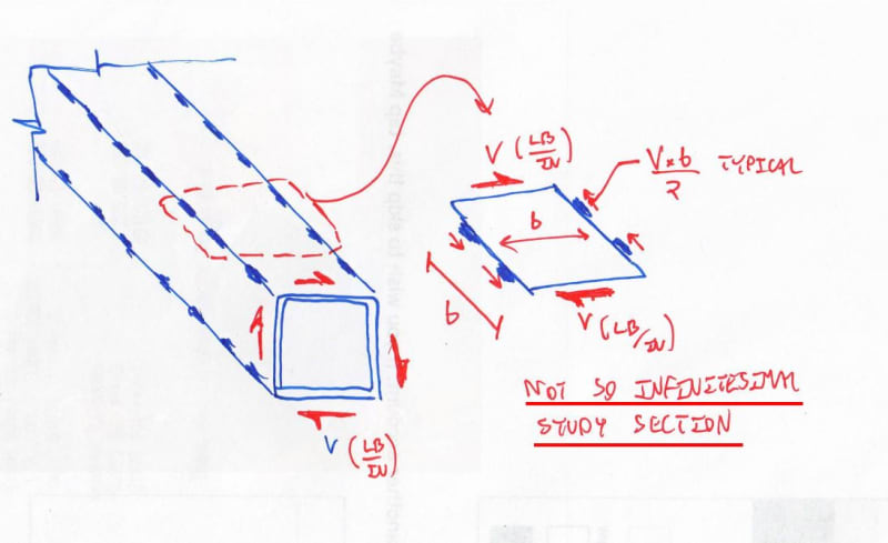
Meh. I absolutely agree that it changes the character of the shear field such that other things are going on but I'm not sure that I see bending as the predominant thing. It would be more tension/compression field under any reasonable weld spacing I think. See the sketch that I'll post in the comment after this one.
TLHS said:
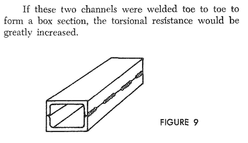
You can physically try this yourself. Fold a piece of card into a box section and twist it. Now take a knife and cut the corners periodically. You're going to significantly increase flexibility and decrease capacity without load continuity.
This is an interesting analogy but is missing something important. The longitudinal dimension of the tube will much greater than the transverse dimension. This means that you've got miles of stitch weld available to resist the shear floor associated with St.Venant shear flow on the cross section. This isn't true of your box unless it's a very unusually proportioned box.
TLHS said:
Once I'm doing that, it's honestly probably faster and cheaper to just lay down a quarter inch weld.
TLHS said:
You only really need to worry about combination of tension/compression due to bending and shear due to torsion when you're high in the stress ranges.
For me, the bigger worry would be warping torsion axial stresses developing in the flanges and combining with bending axial stresses. This is a big part of why I recommended a tube with enough torsional stiffness that it could realistically be expected to shield the WF from picking up torsional load.
canwesteng said:
I can buy the space truss analogy for torsional stiffness, but it seems awfully complicated to check.
TLHS said:
Once I'm doing that, it's honestly probably faster and cheaper to just lay down a quarter inch weld.
With love, gentlemen, I think that you're making mountains out of mole hills with this. If I'm doing it it's:
1) Check against Tc/Jt or whatever to get first minimum for welding.
2) Check that weld spacing is less than 2x diaphragm plate width as I mentioned above.
The end. No big outlay of time or metal energy. While the argument doesn't seem to have garnered much traction, I still content that a) this is almost completely analogous to our usual VQ/It voodo and b) that's an important insight. In a flexural reinforcement, it's not just axial load being resisted. Rather, it's a
gradually varying axial load. And that's significant because it means that you have to pick up shear in the beam as you go and, by the book, that's not possible in the Bernoulli sense between welds. But still we do it and, clearly, it works. Same deal +/-.