Continue to Site

Eng-Tips is the largest engineering community on the Internet

Intelligent Work Forums for Engineering Professionals

  • Congratulations The Obturator on being selected by the Eng-Tips community for having the most helpful posts in the forums last week. Way to Go!

Reducing flange analysis using FEA or Div 1 1

jt1234

Mechanical
Nov 17, 2022
98
Dear all,
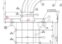
I have a Div. 1 vessel with top 36" nozzle, 600# B16.47 series A, connected to a forging flange with hub ( we call it reducing flange) and a 18" outlet pipe as shown.
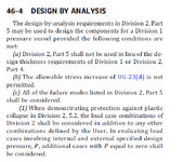
Can this reducing flange be classified as custom made component, not fitting UG-34, UG-39, Appendix 2 or Div 2 Part 4, such that it meets Div. 1 46-4, "Design by Analysis", and using FEA only per Div. 2 Part 5 is acceptable ?

(Note, using UG-34, UG-39 or Appendix 2 will end up much thicker than standard 36" flange)


1747951683215.png


1747953183719.png
 
Replies continue below

Recommended for you

It looks to me that the reducing flange could be considered an Apx 2 integral hub flange, design would presumably be performed per Apx 2-5(2), flange pairs and subsequent rules. The operating and seating loads may not to be identical for each flange of the pair, due to the effect of Hp. Seems the B16.47 flange would govern.

Not clear to me whether you would be obligated to analyze the B 16.47 flange per Apx 2 if it is within its rating.

"Course this may not come out the way you want. Things don't always :)

Whether you can fit it into 46-4 I have no idea, might be a case of agreement among the parties.

Regards,

Mike
 
Don't use the DBA rules to design flanges (unless you want to introduce the concept of "leakage" into your design - and you don't want to do that!). The DBA bolting rules tell you to go back to 4.16 (the VIII-2 equivalent of App. 2) anyway. How would this not qualify for App. 2 / 4.16?
 
As the others wrote, your reducing flange is an Appendix 2 integral flange and it needs to be calculated as per it. And there's not much you can do since most parametres are fixed by the 36" flange.

You can try making both custom designed flanges and calculate them as per appendix 2: maybe you can save some thickness and reduce the number and/or size of bolts.
Not sure it will be cheaper.
 
I agree with jt1234 about UG-39.
The thickness of the reducing flange must be at least equal to that of the 36" flange.
 
What Si-bo says makes a lot of sense. Why use a clunky Series A flange if no one is piping up to it?
 
More clarifications to my post, to see if anyone can help:
This vessel was just fabricated and passed hydrotested and installed already. However, looking back in vendor's hundreds of pages of calc found no calc for this reducing flange.
The reducing flange has the thickness of 123.9 mm, the same as 36" Series A flange. By Appendix 2 or UG-39, it will fail due to such small 18" outlet hub and flange thickness. But it passed per Part 5 using elastic-plastic FEA analysis by vendor after the fact. Since this is custom made forging, will it meet 46-4 (a) such that FEA is acceptable to avoid a redesign and re-fabricate ?
(Note the hub in the sketch is considered as reinforcement. The hub taper ratio will not meet code as it is not considered as a typical flange design. It is considered as a blind and then drill a pipe hole with taper hub as reinforcement.)
 

Part and Inventory Search

Sponsor