This one's for the AISC crowd.
When knocking on the door of this thread, my hope was always that I'd walk away from it with a little candy in hand. And not just a sucker either but, rather, a full sized bag of chips or a three pack of peanut-butter cups. You know, some pearls of wisdom for use in my own, real work using the AISC standard. I believe that I have that now and I'd like to share it, both as an act of friendly dissemination and to provide others an opportunity to critique what I think I now know.
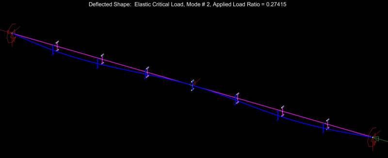
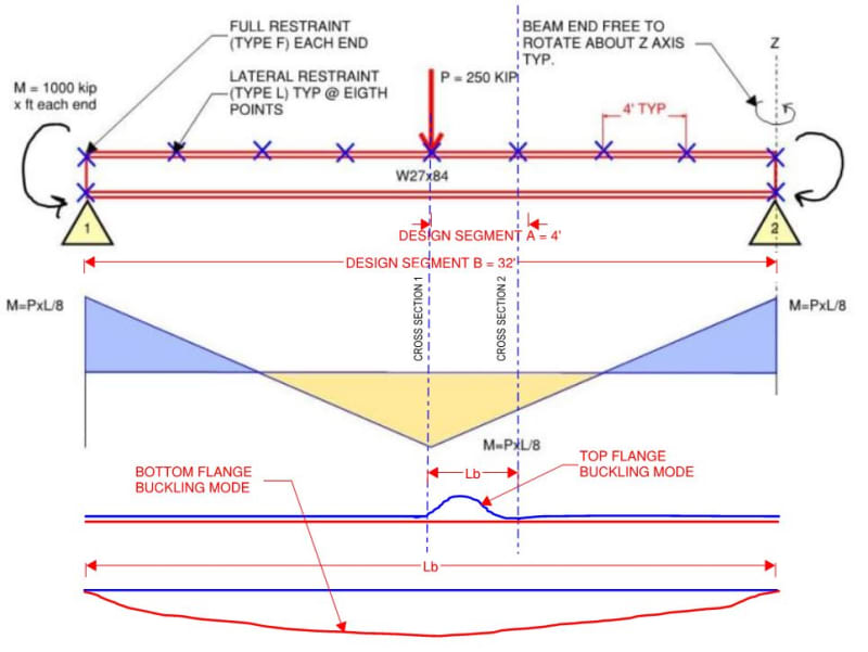
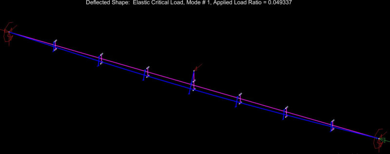
We AISC'ers don't seem to have an under-capacity LTB problem and, as such, do not need to change our ways just yet. That said, the LTB story that now plays in my head is a much richer and more nuanced thing than the one that played in my head prior to this thread. I feel that there's value in that. Without further adieu, here are my before and after LTB stories, with reference to the beam shown below.
KOOTK LTB STORY BEFORE LTB THRILLA IN MANILA 2019
1) Check design segment {A} as top flange buckling @ [Lb = 4']
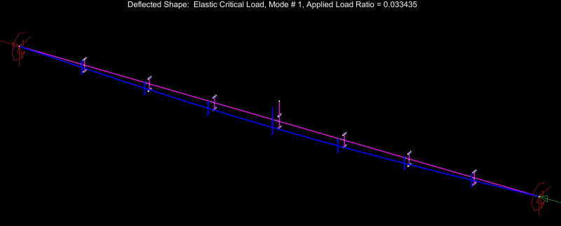
2) Check design segment {B} as bottom flange buckling @ [Lb = 32']
3) Pat self on back for a job well done.
KOOTK LTB STORY AFTER LTB THRILLA IN MANILA 2019
1) Check design segment {A} as top flange buckling @ [Lb = 4']
2) Recognize that #1 implicitly assumed that cross sections 1 & 2, bounding design segment [A], did not rotate appreciably. Marvel at this given that neither cross section is endowed with any physical, rotational restraint in the form of external bracing.
3) Recognize that the two things providing rotational restraint to cross sections 1 & 2 are the St. Venant torsional stiffness of the beam and the warping torsional stiffness of the beam. Further recognize that the warping torsional stiffness will dominate for most wide flange beams.
4) Recognize that the warping torsional stiffness of a wide flange beam basically amounts to the flanges acting as girts spanning horizontally between the rotationally restrained ends of the design segment. For this beam in particular, it's all about the bottom flange performing the girt function. So this is how cross sections 1 & 2 are rotationally stabilized. It's the bottom flange as stabilizing girt.
5) Given that the bottom flange is doing this important girt thing, question whether or not some kind of check should be performed on the bottom flange to ensure that it is strong and stiff enough to do the job. For a simple span beam with no bottom flange compression, no such check is performed. It seems that we are comfortable assuming that an all-tension flange can do the girt job effectively. And that's probably alright given that it really doesn't take much to brace a thing.
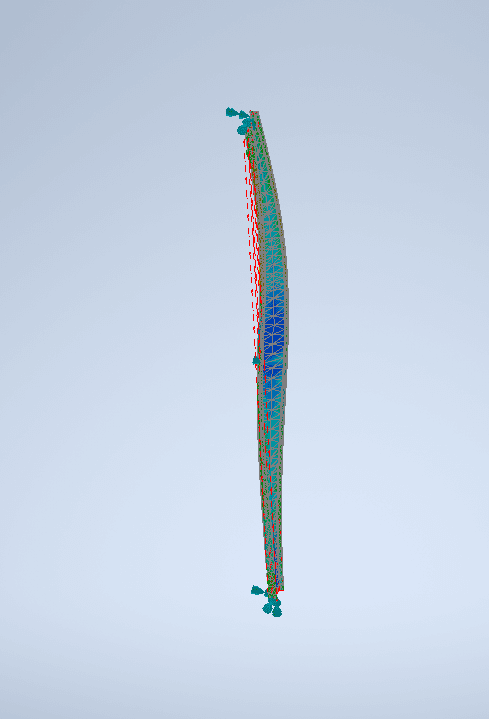
6) Recognize that the bottom flange is in compression over much of its length and will have a tendency to buckle between the ends of the beam. Further recognize that, if the bottom flange is allowed to buckle, it will kick the bottom flange out at cross sections 1 & 2 and, thus, utterly violate the assumption of near zero cross sectional rotation at those locations. What to do?
7) Check design segment
as bottom flange buckling @ [Lb = 32']. In addition to checking for bottom flange buckling in its own right, this check rectifies #6 by allowing us to continue to assume that cross sections 1 & 2 remain rotation free because the bottom flange was not allowed to kick out.
8) Given that negative bending LTB will govern, consider taking advantage of constrained axis LTB which accounts for the benefit of the top flange restraints in the calculation for bottom flange LTB buckling. The trade off is additional calculation complexity. Reject this given that experience has shown that the capacity increase is only on the order of 20% because the center of LTB rotation tends to be pretty close to the top flange even in the absence of the top flange bracing. Deflection concerns probably govern the design anyhow.
9) Pat self on back for a job well done.