HS_PA_EIT said:
KootK - I'm in the US and have had little exposure to AS 4100, so I can't speak to the theoretical background or how it is regularly applied.
No problem at all. For something like this, it's just important to know the background of the person behind the ideas. In your statements, I was hearing a lot of echoes of my own thinking which led me to suspect that we may have similar backgrounds when it comes to steel design. While I values your opinion very much, I'm sure that it will come as no surprise to hear that, on this topic, I'd value it even
more if you were an Aussie practitioner. That whole "horse's mouth" thing, you know?
HS_PA_EIT said:
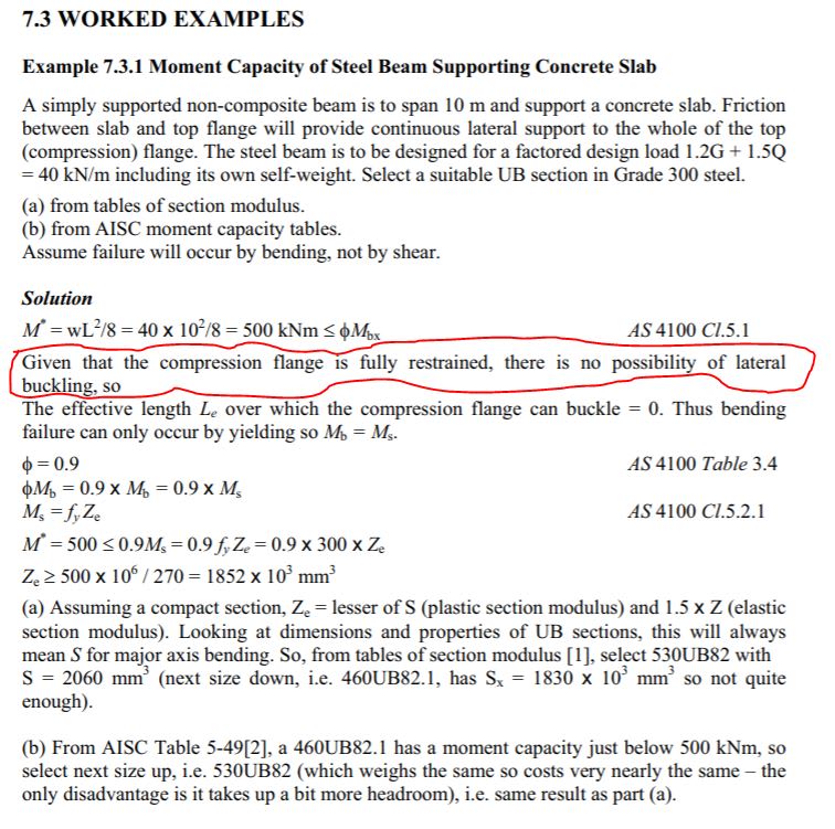
Here is a worked example from "Steel Structures Design Manual To AS 4100" First Edition by Brian Kirke, Senior Lecturer in Civil Engineering Griffith University and Iyad Hassan Al-Jamel, Managing Director ADG Engineers Jordan.
Thanks for the example. It's definitely more cut and dry with simple span beams and continuous compression flange bracing. I'm fairly certain that
all codes give you a pass on LTB in that situation. That said, I agree with your base point that I would reiterate in my own words as follows:
1) The number of possible modes of instability is theoretically infinite.
2) The number of modes of instability of real practical concern is quite limited.
3) It is the purview of both design standards and design engineers to intelligently navigate the juxtaposition of #1 & #2.
HA_PA_EIT said:
Maybe there is effectively zero possibility within the practical limits of real world construction of an LTB mode (constrained axis LTB) occurring before yielding with the compression flange fully restrained.
That is most definitely the case and is why I've been describing the LTB checking of the examples as effectively:
4) Check LTB of the constrained axis buckling mode as I've described it OR;
5) Trust that #4 is bloody awesome and check nothing at all.
The key feature there is simply to recognize that, if you
are going to bother checking any LTB mode, then recognize that the only meaningful check is the constrained axis LTB mode. That, at least as far as it pertains to North American practice where we tackle instability phenomena in a hierarchical fashion as we've already discussed.
The infinite nature of instability is something that seems to factor heavily into the confusion that often surrounds free cantilever design. In that case, you're dealing with a couple of separate LTB buckling modes that occur in unusual close proximity to one another from a potential/strain energy perspective. The top flange is your most effective first brace point but, then, push things a little further and you'll have the bottom flange flopping out to the side. These are really two separate LTB modes rather than a single one. I suspect this is why some codes conclude that you should just be bracing both flanges if your really want to tax a cantilever.
Because no one else will do it for me, I've been trying to generate some high level theoretical explanations of AS4100 of my own. It's still a work in progress but one candidate for "how does it work" is something like this:
1) Only actually give explicit consideration to one buckling mode: the completely unrestrained mode. If capacity is insufficient, add your first brace.
2) Effectively "over-brace" the unrestrained LTB mode by adding more restraints to that LTB mode even though that LTB mode ceased to be a physical possibility, or the critical LTB mode, once the first brace was added.
3) Make the argument that the over-bracing of the unrestrained LTB mode from step #2 effectively eliminates the possibility of any subsequent LTB modes from coming to pass.
I think that this would be consistent with what you're suggesting (and I agree with). There are some big logical gaps to fill in that explanation but, at the least, it would resolve these issues that I have with understanding the AS4100 procedure:
A) How does it address all LTB modes by explicitly considering only one LTB mode (or no actual buckling mode, I'm not sure)? You know, if Human909 is right about that being the case.
B) How can it be that the effective length used is something other than the actual buckling length of the thing doing the bucking? That this is true is clear now from the Yura paper, the FEM models, the design example, and reasonable expectations of physical behavior.