Continue to Site

Eng-Tips is the largest engineering community on the Internet

Intelligent Work Forums for Engineering Professionals

  • Congratulations Ron247 on being selected by the Eng-Tips community for having the most helpful posts in the forums last week. Way to Go!

Rafter and wall plate connection

Kristofer-O

Mechanical
Jun 20, 2025
3
Hi guys,

I'm building myself a garage and I wanted to get your opinion on wall thrust and the rafter and wall plate connection. All the dimensions are in mm.
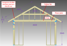
As you see on the picture, I want to connect the rafter to the floor joist using a 45x145 mm material. I was wondering is there a concern that the outward thrust that the rafter exerts wants to bend that piece outward? At the moment I have the collar tie there to prevent the rafters from pushing outward but what would happen if I remove the collar tie? Would then the outward thrust bend the rafters apart?
1750417545759.png

Appreciate all thoughts
 
Replies continue below

Recommended for you

At the end walls (which is what your detail shows) there would be no outward thrust because the wall studs are directly supporting the rafter.

I assume your question is concerning locations other than the end walls, though. In that case, I'd create a structural model or do some hand calcs. to determine the collar tie force. Assuming the collar tie is properly sized, and the connection between the collar tie and rafters is adequate to transfer the thrust force, and the rafters are adequately sized to resist the concentrated load at that location, then I wouldn't be concerned with the outward thrust at the top of the wall.

Without the collar tie, then yes, the rafters will definitely want to spread outwards and you would need to find a means to restrain them.

I probably wouldn't use a collar tie like you show. The higher up on the rafters the collar tie is located, the less effective it becomes. Ideally, the rafters would be connected directly to the floor joists, although you'll obviously need to modify the geometry to make that work. You could also extend the floor joists to meet the rafters at the overhang as another option.
 
To me, this is the best option and the easiest to implement and design around.
I don't love the idea of the seat cut in the rafter occuring inside of the "truss". I would make sure to look at those dimensions closely.
 
I would start with the typical section and not the end walls. If you have overhangs on all sides the top of your roof joists will be lower at the endwalls for your ladder framing unless you notch your roof joists for that framing. Cutting your roof joists for ladder framing on flat is common, but I have never been a fan of that.

What is your code requirement for insulation if heated? The heel height is driven by that requirement. 312 seems large unless you need a lot of insulation. A common detail for rafters like this is a birdsmouth connections.
 
I don't love the idea of the seat cut in the rafter occuring inside of the "truss". I would make sure to look at those dimensions closely.
It wouldn't? I would anticipate the ceiling/floor joists and the rafters to be lapped and so it's just nails/screws in shear. I don't see a seat cut happening at all in the proposed detail.
 
It wouldn't? I would anticipate the ceiling/floor joists and the rafters to be lapped and so it's just nails/screws in shear. I don't see a seat cut happening at all in the proposed detail.
Wouldn't there be a seat cut at the exterior wall for bearing support of the rafters? Or do the rafters solely land on the cantilevered floor joist?
 
The idea was to have no seat cut on the rafters and have the rafter and floor joist on one plane above each other and use the small vertical piece lapped over them to connect the two. So it would be nails in shear.
1750437722953.png
 
Last edited:
As mentioned by Eng16080, I am assuming you are talking about away from the gable end of your structure.

Your drawing appears closer to what is called "stick-built" which is very standard method of wood framing. The location and names of some items in your drawing do not match the typical profile of stick-built (conventional construction). Is your "floor joist" a ceiling joist or is there really going to be floored attic area? Joists (ceiling or floor) typically set on the same wall the rafters are notched into. You show rafters completely on top of joists and not notched. This can be done, but it is more work.

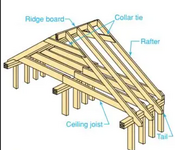
What you call a "collar tie" by definition has to be in the upper third of the rafter, not in the middle. I tend to put them directly under the ridge board, which you do not show one in your drawing. It ties the rafters together for wind uplift and is not intended to resist much (if any) thrust. If you lower it as mentioned in another comment by someone, it is a joist, not a collar tie, and it can assist in resisting thrust.

1750443062621.png
 
I don't love the idea of the seat cut in the rafter occuring inside of the "truss". I would make sure to look at those dimensions closely.
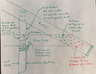
If it's necessary to use the geometry shown by OP and the floor joists are extended to lap over the rafters at the overhang, I wouldn't provide a seat cut. I'd prefer to have a vertical 2x piece lapped over the rafter above the wall. The detail would be something like this. I'd generally consider this detail acceptable, although I'd still prefer framing more like what's shown in the post above by Ron247.

1750455112753.png


What you call a "collar tie" by definition has to be in the upper third of the rafter, not in the middle. I tend to put them directly under the ridge board, which you do not show one in your drawing. It ties the rafters together for wind uplift and is not intended to resist much (if any) thrust. If you lower it as mentioned in another comment by someone, it is a joist, not a collar tie, and it can assist in resisting thrust.
To clear up any potential confusion, in my original post at the top, what I'm referring to as the collar tie is a horizontal framing member which is located closer to the bottom of the rafters. I've probably messed up the correct terminology, but the bottom line is that, you want something as close to the wall top plate as possible to resist the outward thrust of the rafters. In Ron247s post, the ceiling joist is acting in tension to resist the outward thrust, which is ideal in my opinion. The piece labeled as the "collar tie" would be in compression under gravity loads, and is supporting the rafters which possibly results in a smaller rafter size being acceptable. I generally don't use "collar ties" and if I do I typically provide them at every rafter, but with that said, this construction detail has been used for a long time and is generally considered acceptable. I believe the "collar tie" will also tend to increase the outward thrust at the bottom of the rafters, so that is one downside of using it.
 
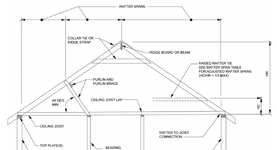
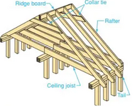
The sketch below is from the 2021 International Residential Code. The sketch is conventional framing. The code in your area probably has a similar sketch.

Note the ridge has 2 options; collar tie or ridge strap. You can pick either method to keep the 2 slopes of the roof connected to each other under wind uplift rather than relying solely on the ridge board connection. The rafter to ridge connection is pretty good under gravity loads but not extreme uplift. Collar ties and straps have to be no more than 4' on center spacing, which typically means every other rafter, therefore, they would not reduce the unsupported length of the rafter without a collar tie. Also note, lower in the sketch, they show the "raised rafter tie" which is the other member we have discussed that has the same appearance as a collar tie, but a different location. Collar ties are in the upper third and raised rafter ties are limited to the lower third. Similar appearances but intended different uses. The unsupported length of the rafter is dictated by the location of what they are calling the "purlin and purlin brace". A better name would have been rafter bracing because that is what that entire assembly is doing; it is reducing the clear span of the rafter.

I don't mentally deal in metric, so the dimensions of the drawing might as well be in light-years for me to get a feel for what you have. In areas where the roof design is governed by Roof Live Load, when we use 2x6s at 2' on center for rafters, the rough estimate of how far you can go laterally until you need purlin bracing is 12 feet regardless of pitch.

Also note they say "Ridge Board or Beam" but there is a distinction between the 2. Ridge Boards are essentially not structural while Ridge Beams are structural. Properly designed Ridge Beams are used to eliminate or reduce the need for ceiling joists and raised rafter ties.

As far as installing collar ties (also called wind braces), please install them high enough someone can walk under them without ducking when possible. Less lumber and a lot easier to navigate the attic for the next 100 years. Code says "upper third" but I put them close to the ridge when possible.

1750458476311.png
 
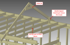
Are you just not wanting a seat cut (aka bird's mouth) for some reason? You show your rafter and joist in alignment to each other. That makes a connection with a torque to it unless you block both sides. If you use one side, alternate them.
 
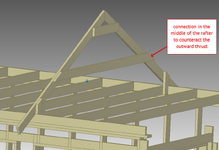
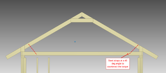
The birds mouth is totally an option, i was just wondering, maybe i can do without. Since I don't connect the rafter directly to the ceiling joist but use a lapped connecting piece, then I have a connection with a torque. Now Im thinking how can I reduce that?
I could use blocking on both sides of the rafter or install so to say a "collar tie" that is in the middle of the rafters to reduce the outward thrust and the torque in the connection. Or a third option add steel straps to connect the rafter to the ceiling joist at a 45 deg angle.
1750490365961.png

1750490386889.png

1750490458585.png
 
You show your rafter and joist in alignment to each other.
If this is in reference to the sketch I made, the rafter and joist aren't aligned. They're lapped. The joist would be on one side of the rafter and the vertical on the other. Between the vertical and joist would be a spacer block. I didn't draw it exactly correct in terms of the dashed (hidden lines).

Concerning the birdsmouth, I see no good reason to do that here as long as the connections shown can transfer the loads. (No clue what OP's loads are.)
Your sketch does not have them aligned as you stated, but the OP's 2nd posting and sketch has them aligned.

Kristofer, are you in a heavy snow load area? This looks like a 1-car garage which around here would be about 15' wide or less in total width. Structurally, every system we have discussed can work. I do see keeping everything aligned during construction being a challenge if you do not allow for manufacturing tolerances in your materials. The vertical blocks will be the challenge. Same height and installed to the same degree of plumbness almost mandatory.
 
Kristofer, is there a reason why you can't frame it like this:
1750535338549.png
IMO, all other options (including my sketch) are inferior to this kind of detail, where the ceiling joists are lapped over the rafters. In all three of your sketches above, you're creating unnecessary complications. I wouldn't want to use options 1 or 3, and option 2 with the horizontal piece at midheight isn't great either. There will be a very high tension force with it half the way up. You've gotta run the numbers on this. I would lower the horizontal piece as far down on the rafters as possible.
 

Part and Inventory Search

Sponsor