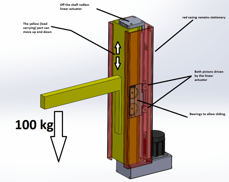
Look in your very first picture at the "bearings to allow sliding". They are very close to each other. Why does that matter? Because the force that each bearing sees (and therefore the force that it imparts to the slide surface) is directly related to the distance from the other bearing, inversely. For example, if a 200 lb payload is 12 inches horizontally from the center of the upper bearing it creates a 2400 in-lb moment about that bearing. Lets assume the lower bearing is 6 inches below the upper bearing. That means it would see a 400 lb load to balance that moment. Both bearings would see 400 lb loads in opposite directions. That also means that your vertical rail surfaces would see 400 lb point loads. The shell appears to be extruded so I am assuming aluminum. I don't think that will work. I would strongly recommend you separate your bearings as much as possible, at least 12 inches apart.
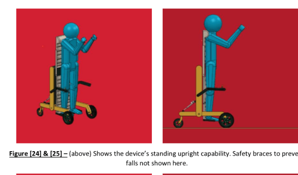
That separation will affect your final configuration. Look at Fig 23. In that position the lower bearing on the lift carriage would be at least 6 inches off the floor, probably more like 8 inches. That means the upper bearing would be 20 inches off the floor in the full down position. Now look at fig. 25. It looks like the lift carriage has traveled upward maybe 30 inches? In that position the upper bearing would be 20 + 30 = 50 inches off the floor, which means the stationary rails will have to be at least that tall. This has nothing to do with amplifying the stroke of the actuator. This is simple linear guidance support, not even considering how it is powered. You could of course use a telescoping travel mechanism like one sees on some fork trucks or manlifts, with the accompanying complications and load calculations. But either way you should keep as much separation as possible between the bearings on the lift carriage.
If you do insist on keeping some travel amplification, be aware that you are magnifying the actual load on the actuator by the same ratio. Double travel = double force, regardless of whether the mechanism is rack and pinion or chain and pulley.
If it were me I would avoid rack and pinion for several reasons. Alignment of travel is ABSOLUTELY critical. You MUST maintain the exact same mesh at all times through travel. A tiny variation (from small frame deflections, etc) makes a huge difference in the load and friction that individual teeth see. The teeth will wear out very quickly and eventually fail. Think about this - there is a reason that commercial gearboxes operate with the gears in an oil bath. If I were forced to design some travel amplification (First I would resist it strongly) I would use a roller chain and sprocket, which the same method used on almost all telescoping forktrucks. Anchor a chain at one end. Send it up and over a sprocket driven upward by your actuator. And tie the other end to the lift carriage. Easy, peasy. Alignment is not an issue and neither is lubrication.
So, after you've done all this designing, building, trialing, redesigning, rebuilding, retrialing, redesigning again, building again, and retrialing again, you will arrive at this conclusion - I should have used a commercially available linear guide arrangement, a commercially available actuator, no amplification, and saved myself lots of time, money, and heartache.