Continue to Site

Eng-Tips is the largest engineering community on the Internet

Intelligent Work Forums for Engineering Professionals

  • Congratulations 3DDave on being selected by the Eng-Tips community for having the most helpful posts in the forums last week. Way to Go!

PSV Inlet and Outlet Pressure Drop Calculation Question

Pavan Kumar

Chemical
Aug 27, 2019
405
Hi All,

I sized a PSV downstream of a Control Valve for its wide-open failure case and got a 6"Q8" PSV. The required relief rate is 254107 lb/hr with Oxygen as the fluid. The rated capacity of the PSV is 294,851 lb/hr with 10% overpressure. I tried to size the inlet/outlet lines to this PSV. The PSV inlet line is 2 ft long and the outlet pipe is 4 ft long with an elbow. The PSV is to be installed on the 6" line downstream of the control valve with option to move it to the 12" line.


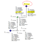
View attachment 10578

My questions:

1. The PSV Inlet pressure drop should be calculated from the source of pressure, in this case from the control valve outlet flange or can I calculate it from the reducing inlet to PSV Inlet?.

My Calculations : (i) When I used 6" inlet line taking off 6" line the inlet pressure drop is 13 psi, which is 4.8% of the PSV Set pressure. I used AFT Arrow to do these calculations. If install the PSV on the 12" line and use 8" inlet with a 8"X6" reducer at the PSV inlet I still 4.8% inlet DP. Also this calculating the pressure drop from the TEE inlet and not the Control Valve outlet flange. Is there an option that you can suggest to reduce this DP to less than 3%. I can go with a Pilot Operated PSV option whose capacity is not reduced by the inlet line pressure losses. But that is an expensive option and I want to avoid it if possible as the body and trim will be made of Monel for Oxygen service.

2. For the outlet side, I used a 8"X12" expander, followed by 12" Sch 10 pipe that is 4 feet long and calculated the pressure drop to be 7.2% of the PSV Set pressure. The velocity is sonic across the PSV, becomes sub-sonic in the outlet line after the 8"X12" expander and reaches sonic at the pipe exit. I want to know if this acceptable. If I use 10" pipe then the pressure drop goes to 9.5% of set pressure. My AFT Arrow model screens shot for the 12" pipe option is shown below. You can see that even though I want 0 psig at the pipe exit, the model achieves only 0.42 psig. If I use 10" pipe then it reaches 6.7 psig (result pasted as well).

I also did calculations using my spreadsheet using isothermal compressible equation and I get 4% for the Inlet pressure drop and 22% for the outlet pressure drop. My excel calcs are close for the inlet side(4% vs. 4.8%) but there is large difference for the outlet side ( 22% vs. 7.2% ). My spreadsheet is attached also. I did this to cross-check AFT Arrow calcs. I wanted to understand why these are so different.

12" Outlet Pipe Option
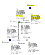
1749565072954.png

10" Outlet Pipe Option:

1749565148597.png


Thanks and Regards,
Pavan Kumar
 

Attachments

  • O2 Pressure Reducing Station - Calculations.xlsx
    295.8 KB · Views: 6
Last edited:
Replies continue below

Recommended for you

PSV inlet line : Standard practice would be to include the control valve exit into the inlet line dp calcs.

PSV exit line : Standard practice is to keep exit line velocity at <0.7Mach for brownfield applications, preferably <0.5Mach for greenfield, even if your exit line dp < 10% of PSV set pressure at process design relief flow.
Thanks George.

Pavan Kumar
 
My Calculations : (i) When I used 6" inlet line taking off 6" line the inlet pressure drop is 13 psi, which is 4.8% of the PSV Set pressure. I used AFT Arrow to do these calculations. If install the PSV on the 12" line and use 8" inlet with a 8"X6" reducer at the PSV inlet I still 4.8% inlet DP. Also this calculating the pressure drop from the TEE inlet and not the Control Valve outlet flange. Is there an option that you can suggest to reduce this DP to less than 3%. I can go with a Pilot Operated PSV option whose capacity is not reduced by the inlet line pressure losses. But that is an expensive option and I want to avoid it if possible as the body and trim will be made of Monel for Oxygen service.

If you install a 12" x 12" tee for the branch take-off then you will only have a 0.5 psi pressure drop in the connection since the tee branch connection pressure drop will be based on the velocity in 12" branch not 8" branch. Then with 12" x 8" reducer (12 ft equiv. L) and 2 feet of straight 6" pipe without need for reducer you will have less than 4.5 psi drop in this section for a total of 5.0 psi drop in inlet not counting the pressure drop due to increase in velocity from 12" to 6".

Also I am not getting 13 psi drop in inlet based on your configuration. I only get about a 6 psi drop with 12"x8" branch tee then 8" x 6" reducer plus 2 ft of 6" pipe. This is using 10 feet equivalent length of 12", 40 feet of 8" (for 12"x8" branch tee) and 10 feet of 6" pipe (8"x6" reducer plus 2 feet straight pipe). Maybe I have a mistake somewhere but I can't find it.
 
Last edited:
I was just looking at your inlet calculations. I think what you did wrong is that you included all pipe pressure drop under one calculation based on 6" line size. If you do this then the tee branch does give about 9 psi drop as you show. However, if you do a separate calculation for tee branch based on 8" size then the pressure drop through the tee is only about 3 psi. Then a do a separate calculation for the pressure drop through the reducer and 2.5 ft. of 6" pipe based on 6" pipe size and velocity.
 
Looking at your outlet calcs I see you made a mistake by including one 90 deg elbow in calculation of the 8" pipe segment - it is already accounted for as 12" in calc sheet 2. I also see some mistakes in your calcs for acoustic velocity value = (gkR(2/(k+1))T)^0.5 not what you show. Also for 12" the outlet pressure is not 14.7 psia as you assumed since velocity is sonic at exit so pressure will be above atmospheric at tip of pipe (and keep mach no greater than 0.8 for vent to atmos.). I will continue checking tomorrow if I have time.
 
Last edited:
Looking at your outlet calcs I see you made a mistake by including one 90 deg elbow in calculation of the 8" pipe segment - it is already accounted for as 12" in calc sheet 2. I also see some mistakes in your calcs for acoustic velocity value = (gkR(2/(k+1))T)^0.5 not what you show. Also for 12" the outlet pressure is not 14.7 psia as you assumed since velocity is sonic at exit so pressure will be above atmospheric at tip of pipe (and keep mach no greater than 0.8 for vent to atmos.). I will continue checking tomorrow if I have time.
Hi Snickster,

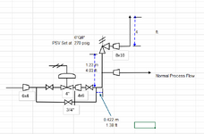
Due to changes in the PSV location I updated my PSV Sizing, PSV Inlet/Outlet Line Pressure Drop calculations and took care of your comments above. Kindy find the udpated file attached. Please let me know if you still see any mistakes. The new location is show below.

1749670376133.png

Thanks and Regards,
Pavan Kumar
 

Attachments

  • O2 Pressure Reducing Station - Calculations.xlsx
    374.4 KB · Views: 3
I am looking over your calcs for 8" x 10" outlet line, have not got to the rest of calcs. One thing I have question about. You indicate that the exit pressure of the 10" vent pipe is 35.3 psig. How did you calculate this? I only get about 6.8 psig at 274,824 lb/hr at 92 deg F

From your original post you appeared to indicate that you were confused about how the Fathom model was getting 6.7 psig outlet pressure in the 10" and not atmospheric at the outlet, which appears to indicate you don't fully understand compressible fluid flow and what happens in a pipe when you reach sonic flow conditions. I suggest you read some technical discussion on compressible flow in piping. I will check if I have any references that goes into detailed explanation for you.

In short, when flow is subsonic in the vent pipe exits, the pressure at the inside tip of the pipe at the exit equals atmospheric pressure. As the flow increases the velocity also increases until the velocity reaches sonic, and at this time the pressure at the pipe tip inside the pipe exit is still atmospheric. If the flow rate (mass flow rate) increases beyond this point the velocity can't increase to accommodate the increase in flow since the limiting velocity in a pipe is sonic (this is what you need to understand and read up on). What happens is the velocity stays sonic and does not increase, but the pressure builds up inside the tip of the pipe exist to above atmospheric. This is because at a higher tip pressure at same sonic velocity of flow the mass flowrate is higher. This is how the higher mass flow rate is accommodated for. The pressure will build up to whatever is required inside the pipe tip exit as you keep increasing the mass flowrate above that value where sonic flow just starts. So the pipe exit can build up to 100 psig or more if required, as long as the total backpressure at the relief valve discharge does not reduce the relief rate of the relief valve. The total back pressure at the relief valve discharge is this pipe tip exit pressure plus the frictional pressure drop.

Other minor things I see on your 10" pipe calc:

Sonic velocity a' should equal = SQRT (gkRT) Where T is the temperature when sonic flow is reached = (2/(k+1))(To) Where To is stagnation temperature approx 92 F.

For long radius 1.5D elbow L/D=16 not 30, which is for a threaded small sharp bend.

There is no thru tee in the 10" section as you included in the fitting list

The table at the bottom lists the 10" outlet temperature as 33.33 deg C which is not correct. 33.33 deg C is the subsonc low velocity temperature of the fluid upstream of the relief valve. When the flow is sonic the sonic temperature is (2/(k+1))(T) = (2/2.4)(552 R) = 460 R = 0 deg F.

When I have time I will look over the rest. I did look at your relief valve set-up and think it will be better on the 12" header. As it is on the 6" CV discharge there is a high pressure drop in the 6" which will exceed the 3%. Also the relief valve orifice is extremely oversized so there will be big issues with valve chattering wanting to close as soon as it opens due to large pressure drop on inlet and discharge volume of flow so much higher than the input flow from the wide open control valve. If on 12" header there is enough volume in the header so that as the relief valve starts relieving the pressure in the 12" should be maintained without dropping too fast causing chattering of the relief valve and in my opinion you only have to do inlet pressure drop for the inlet piping of the relief valve and not back to the exit of the CV.
 
Last edited:
I found a resource technical discussion on the internet about sonic flow in piping coincidently prepared by AFT attached.
 

Attachments

  • sonic-choking-in-compressed-systems-asme.pdf
    829 KB · Views: 4
Also I don't know if it is against any Code but I believe the exit velocity of a vent pipe should be kept to below 0.8 sonic but greater than 500 ft/sec (for dispersion of heavier than air gases) in accordance with typical client specifications. This will require upsizing your vent.
 
Also I would try to get the relief valve orifice size closer to what the calculated required is. You have an extremely oversized orifice. ASME orifice (rather than API) sizes have a size very close to what you calculated. See link:

That article contains incorrect information. It is a situation yet again, on getting effective (API) and Actual (ASME) orifice areas and coefficients mixed up. Use only Actual areas and coefficients together or Effective areas and coefficients. Never an actual area and effective coefficient or vice-versa. See also a FAQ I wrote here on Eng-Tips a while back https://www.eng-tips.com/forums/1203/faqs/2084
 
I am looking over your calcs for 8" x 10" outlet line, have not got to the rest of calcs. One thing I have question about. You indicate that the exit pressure of the 10" vent pipe is 35.3 psig. How did you calculate this? I only get about 6.8 psig at 274,824 lb/hr at 92 deg F

From your original post you appeared to indicate that you were confused about how the Fathom model was getting 6.7 psig outlet pressure in the 10" and not atmospheric at the outlet, which appears to indicate you don't fully understand compressible fluid flow and what happens in a pipe when you reach sonic flow conditions. I suggest you read some technical discussion on compressible flow in piping. I will check if I have any references that goes into detailed explanation for you.

In short, when flow is subsonic in the vent pipe exits, the pressure at the inside tip of the pipe at the exit equals atmospheric pressure. As the flow increases the velocity also increases until the velocity reaches sonic, and at this time the pressure at the pipe tip inside the pipe exit is still atmospheric. If the flow rate (mass flow rate) increases beyond this point the velocity can't increase to accommodate the increase in flow since the limiting velocity in a pipe is sonic (this is what you need to understand and read up on). What happens is the velocity stays sonic and does not increase, but the pressure builds up inside the tip of the pipe exist to above atmospheric. This is because at a higher tip pressure at same sonic velocity of flow the mass flowrate is higher. This is how the higher mass flow rate is accommodated for. The pressure will build up to whatever is required inside the pipe tip exit as you keep increasing the mass flowrate above that value where sonic flow just starts. So the pipe exit can build up to 100 psig or more if required, as long as the total backpressure at the relief valve discharge does not reduce the relief rate of the relief valve. The total back pressure at the relief valve discharge is this pipe tip exit pressure plus the frictional pressure drop.

Other minor things I see on your 10" pipe calc:

Sonic velocity a' should equal = SQRT (gkRT) Where T is the temperature when sonic flow is reached = (2/(k+1))(To) Where To is stagnation temperature approx 92 F.

For long radius 1.5D elbow L/D=16 not 30, which is for a threaded small sharp bend.

There is no thru tee in the 10" section as you included in the fitting list

The table at the bottom lists the 10" outlet temperature as 33.33 deg C which is not correct. 33.33 deg C is the subsonc low velocity temperature of the fluid upstream of the relief valve. When the flow is sonic the sonic temperature is (2/(k+1))(T) = (2/2.4)(552 R) = 460 R = 0 deg F.

When I have time I will look over the rest. I did look at your relief valve set-up and think it will be better on the 12" header. As it is on the 6" CV discharge there is a high pressure drop in the 6" which will exceed the 3%. Also the relief valve orifice is extremely oversized so there will be big issues with valve chattering wanting to close as soon as it opens due to large pressure drop on inlet and discharge volume of flow so much higher than the input flow from the wide open control valve. If on 12" header there is enough volume in the header so that as the relief valve starts relieving the pressure in the 12" should be maintained without dropping too fast causing chattering of the relief valve and in my opinion you only have to do inlet pressure drop for the inlet piping of the relief valve and not back to the exit of the CV.
Hi Snickster,

Thank you very much for taking time to review my calculations. Yes I am indeed not very clear on Compressible Flow especially when the flow reaches sonic velocity. I think I get full understanding of this I will use AFT Arrow for my calculations. I will read the article that you sent me and get better at this. Also I have been using Isothermal Equation and that is the reason why I used 33.33 Deg C ( 92 Deg F) at the pipe exit. I used 35.3 psig pressure at the pipe exit to make sure the Mach Number is less 0.8. I used this pressure ( 35.3 psig) and then back calculated the pressure drop in the 10" pipe section and then the 8" section. Please explain me how you got 6.7 psig at the pipe exit. With the required relief rate of 1860123.147 lb./hr., I calculate a required orifice area as 6.97 inch2. So I have to use the next bigger orifice which "P" orifice (Orifice area =11.05 in2). "N" orifice has 4.38 in2 orifice area. I cannot move the PSV to the 12" section as the inlet pressure from Control Valve exit to the PSV Inlet increases.

Thanks and Regards,
Pavan Kumar
 
Thank you very much for taking time to review my calculations. Yes I am indeed not very clear on Compressible Flow especially when the flow reaches sonic velocity. I think I get full understanding of this I will use AFT Arrow for my calculations. I will read the article that you sent me and get better at this. Also I have been using Isothermal Equation and that is the reason why I used 33.33 Deg C ( 92 Deg F) at the pipe exit.

OK that makes sense for using subsonic flow temperature in the isothermal equation for calculating friction losses

I used 35.3 psig pressure at the pipe exit to make sure the Mach Number is less 0.8.

I think I know what you are saying. You are saying that it takes an exit pressure of 35.3 psig to maintain the velocity at 0.8 Mach. The only problem is that this is not the real pressure that the pipe discharges to. If it discharges to the atmosphere the pressure it discharges to is 14.7 psia or 0 psig.

I used this pressure ( 35.3 psig) and then back calculated the pressure drop in the 10" pipe section and then the 8" section. Please explain me how you got 6.7 psig at the pipe exit.

As I explained in my previous post, the velocity cannot exceed sonic Mach 1 in a pipe and Mach 1 sonic velocity if it exist will always exist at the end of a pipe of a particular diameter. For instance for a given flow rate if you have sonic velocity say in a 8" pipe that connects to say a 12" pipe then sonic velocity will exist in the 8" pipe at the very end at the connection to the 12", then in the 12" the velocity will be subsonic again due to the increase in flow area. Or in your case you have a 10" discharge to atmospher the sonic velocity occurs at the end of the 10" just at the pipe exit but decreases to subsonic upstream due to increase in pressure upstream due to friction. Since velocity cannot exceed Mach 1 which occurs at the pipe exit, then if the flow increases beyond the point where the velocity reaches Mach 1 at 14.7 psia then the only way the system can adjust to allow more flow is for the exit pressure inside the pipe to increase at same velocity.

For your piping here is the calculation:

Sonic Velocity c = SQRT (gkRT) = SQRT (32.2(1.4)(1545/32)(2/2.4)(552)) = 1000.6 ft/sec

Where:

c=ideal sonic velocity at Mach 1.
g = gravitational constant 32.2 ft/sec^2
k = Ratio of specific heats Cp/Cv
R = Gas constant = 1545 ft-lb/pmol divided by MW molecular weight
T = temperature when fluid reaches Mach 1 = (2/(k+1))(To) Where To is stagnation temperature = approx flowing temperature at low velocities

So 1000.6 ft/sec is the maximum possible velocity in the pipe at the exit.

So here is how you determine the exit pressure of the pipe using the ideal gas equation (neglecting compressibility factor):

P(144)V(A) = m R T

P= pressure psia
V= velocity ft/sec
A = exit area of pipe ft^2
Note V*A equals actual volumetric flowrate in ft^3/sec
m = mass flowrate lb/sec (pound weight not mass)
R = 1545/MW
T= actual outlet temperature as indicated above when flow is sonic

As I said in my previous post the way the system accommodates increase in flow, since the velocity is fixed at 1000.6 ft/sec maximum sonic speed, and all other factors in the above equation are fixed too, except for pressure, then pressure must increase if the mass flow increases m. If you have a relief valve on a vessel the mass flow say at blocked flow can vary from zero to any maximum calculated value. At some value of mass flow if you plug into the above equations at P = 14.7 atmospheric and solve for V velocity then you will get exactly sonic velocity 1000.6 ft/sec. Any increase in mass flow above this value, considering all other parameters in the equation are fixed (including velocity = 1000.6 max sonic velocity) except pressure, will cause the exit pressure calculated to be greater that 14.7 psia. So what happens is that the pipe exit pressure inside the pipe tip actually becomes greater than atmospheric. There is therefore a pressure discontinuity between the pressure inside the pipe exit and the atmospheric pressure. This pressure/energy is dissipate in irreversible shock waves at the fluid exits the pipe.

For your 10" pipe:

P(144)(1000.6)(Pi/4)(10.2/12)^2 = (274,824/3600)(1545/32)(2/2.4)(552)

P = 21.5 psia = 6.8 psig

Note that this is more in line with what you show AFT calculated at pipe exit of 6.7 psig.

So here is how you determine if the flow is subsonic or sonic using the above equation. Plug in the calculated sonic velocity, actual mass flow, and flowing temperature, R value and pipe exit area in the above equation.

If the calculated pressure is below the pressure that the pipe discharges to - for atmospheric discharge less than 14.7 psia - then the flow is subsonic.

If the calculated pressure equals the pressure that the pipe discharges to - for atmospheric discharge equal to 14.7 psia - the flow has just reached sonic.

If the calculated pressure is above the pressure the pipe discharges to - greater than 14.7 psia for atmospheric discharge - the flow is sonic at same sonic velocity but the mass flow is above the flow required to just reach sonic, and the pressure will then build up to whatever value required at the exit as long at the pressure build up at the exit does not cause the flow to decrease. (Such as flow through a relief valve will theoretically not decrease with backpressure as long as the back pressure stays below the critical flow value where sonic flow exist in the nozzle of the relief valve orifice - for air Pcf = 0.528 P1 as you indicate on the first sheet of you excel calculation)


With the required relief rate of 1860123.147 lb./hr., I calculate a required orifice area as 6.97 inch2. So I have to use the next bigger orifice which "P" orifice (Orifice area =11.05 in2). "N" orifice has 4.38 in2 orifice area. I cannot move the PSV to the 12" section as the inlet pressure from Control Valve exit to the PSV Inlet increases.

I think you going to have operational issues if the orifice is that much oversized. I don't know what you can do. Maybe see if any manufacturer can provide an orifice flow closer to required, or use two relief valves with N orifices in parallel.

I believe you need to install on 12". The pressure drop back to the CV outlet will not be that significant. However the 12" will serve to maintain pressure without dropping significantly when the relief valve pops even if the valve is oversized a little. The pressure drop in the 12" will be based on the change in volume of stored gas in the 12" which is due to the flow in from the CV minus the amount the relief valve is oversized so it will not drop in 12" as suddenly as if the relief valve was attached directly to the discharge of the CV.
 
Last edited:
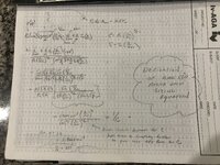
You might be interested to know that you can derive the API 520 relief valve capacity equation using the same ideal gas equation shown above by setting the velocity at sonic in PSV orifice, pressure at Pcf in PSV orifice and temperature at 2/k+1 (T) in the PSV orifice, and also including the compressibility factor Z on the right side of the equation. I have derived a while back per the attached not including the correction factors Kb, Kc, Kd.
 

Attachments

  • IMG_2250a.JPG
    IMG_2250a.JPG
    2.6 MB · Views: 4

Part and Inventory Search

Sponsor