Continue to Site

Eng-Tips is the largest engineering community on the Internet

Intelligent Work Forums for Engineering Professionals

  • Congratulations Ron247 on being selected by the Eng-Tips community for having the most helpful posts in the forums last week. Way to Go!

PSV Inlet and Outlet Pressure Drop Calculation Question 1

Pavan Kumar

Chemical
Aug 27, 2019
407
Hi All,

I sized a PSV downstream of a Control Valve for its wide-open failure case and got a 6"Q8" PSV. The required relief rate is 254107 lb/hr with Oxygen as the fluid. The rated capacity of the PSV is 294,851 lb/hr with 10% overpressure. I tried to size the inlet/outlet lines to this PSV. The PSV inlet line is 2 ft long and the outlet pipe is 4 ft long with an elbow. The PSV is to be installed on the 6" line downstream of the control valve with option to move it to the 12" line.


View attachment 10578

My questions:

1. The PSV Inlet pressure drop should be calculated from the source of pressure, in this case from the control valve outlet flange or can I calculate it from the reducing inlet to PSV Inlet?.

My Calculations : (i) When I used 6" inlet line taking off 6" line the inlet pressure drop is 13 psi, which is 4.8% of the PSV Set pressure. I used AFT Arrow to do these calculations. If install the PSV on the 12" line and use 8" inlet with a 8"X6" reducer at the PSV inlet I still 4.8% inlet DP. Also this calculating the pressure drop from the TEE inlet and not the Control Valve outlet flange. Is there an option that you can suggest to reduce this DP to less than 3%. I can go with a Pilot Operated PSV option whose capacity is not reduced by the inlet line pressure losses. But that is an expensive option and I want to avoid it if possible as the body and trim will be made of Monel for Oxygen service.

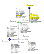
2. For the outlet side, I used a 8"X12" expander, followed by 12" Sch 10 pipe that is 4 feet long and calculated the pressure drop to be 7.2% of the PSV Set pressure. The velocity is sonic across the PSV, becomes sub-sonic in the outlet line after the 8"X12" expander and reaches sonic at the pipe exit. I want to know if this acceptable. If I use 10" pipe then the pressure drop goes to 9.5% of set pressure. My AFT Arrow model screens shot for the 12" pipe option is shown below. You can see that even though I want 0 psig at the pipe exit, the model achieves only 0.42 psig. If I use 10" pipe then it reaches 6.7 psig (result pasted as well).

I also did calculations using my spreadsheet using isothermal compressible equation and I get 4% for the Inlet pressure drop and 22% for the outlet pressure drop. My excel calcs are close for the inlet side(4% vs. 4.8%) but there is large difference for the outlet side ( 22% vs. 7.2% ). My spreadsheet is attached also. I did this to cross-check AFT Arrow calcs. I wanted to understand why these are so different.

12" Outlet Pipe Option
1749565072954.png

10" Outlet Pipe Option:

1749565148597.png


Thanks and Regards,
Pavan Kumar
 

Attachments

  • O2 Pressure Reducing Station - Calculations.xlsx
    295.8 KB · Views: 11
Last edited:
Replies continue below

Recommended for you

Hi Snickster,

For your piping here is the calculation:

Sonic Velocity c = SQRT (gkRT) = SQRT (32.2(1.4)(1545/32)(2/2.4)(552)) = 1000.6 ft/sec

Where:

c=ideal sonic velocity at Mach 1.
g = gravitational constant 32.2 ft/sec^2
k = Ratio of specific heats Cp/Cv
R = Gas constant = 1545 ft-lb/pmol divided by MW molecular weight
T = temperature when fluid reaches Mach 1 = (2/(k+1))(To) Where To is stagnation temperature = approx flowing temperature at low velocities

The formula that you wrote for the Acoustic velocity calculation is assuming that the temperature at the pipe exit is calculated using T*=To * (2/k+1). But this is based on the assumption that flow is isentropic that is adiabatic and frictionless. The flow is in the pipe is adiabatic but not frictionless so I think the correct formula would be as shown below. Kindly let me know if you agree.

1750194306975.png

where T1 is the temperature at the pipe inlet(92 Deg F) and T2 at the pipe exit. Since in our case we ae expecting sonic velocity at the pipe exit, Nma2=1 and T =T*. The equation becomes

T*/T1 = (2/(k+1))*{1+[(k-1)/2]*Nma,1^2)}

so T* can be calculated only after Nma,1 is calculated, which I think can be calculated using the adiabatic compressible flow equation shown below by substituting the values.

1750194913444.png

where,

f is Darcy friction factor,
L/D is the total straight length including the equivalent if the fittings.
k is the ratio of specific heats.

Once Nma,1 and T* are known we can calculate the pipe exit(P) using the formula

P* a *A = mRT*

where,
a= sonic velocity calculated using a=SQRT(gckRT*/M)
A= Area of pipe exit,ft2
m =PSV rated capacity in lb/hr
R = 1545 lbf-ft3/ft2-lbmole-Deg R
T=T*

I am going to use the adiabatic compressible frictional loss equation for my pressure drop calculations

1750194867143.png

Thanks and Regards,
Pavan Kumar
 

Attachments

  • 1750194041573.png
    1750194041573.png
    2.4 KB · Views: 1
  • 1750194097483.png
    1750194097483.png
    2.4 KB · Views: 2
  • 1750194492930.png
    1750194492930.png
    6.1 KB · Views: 2
Given a length of pipe with a flowing gas with friction. Any pressure (energy) loss due to friction is put back into the fluid if the process is adiabatic. Therefore the velocity increase due to pressure decrease due to friction has to come from the change in enthalpy of the fluid without any additional energy input. In other words without a velocity increase due to pressure decrease the upstream and downstream enthalpy would be equal. This could occur if as friction occurs the cross-sectional area of the pipe is increased just enough so the velocity remains constant. The following equation can be used to find the downstream temperature.

dH = dKE

Cp (T1-T2) = (V2^2 - V1^2)/(2g(778))

However assuming velocity at T1 upstream is low subsonic (100 - 200 ft/sec or so) then you can assume V1 is negligible and T1 is close to stagnation temperature To. This is what I was doing in my previous post as a short cut to calculating the actual stagnation temperature To base on T1 and velocity V1 since you only provided a flowing temperature of 92 F but not the stagnation temperature To. So if you take this shortcut then above equation reduces to:

Rearranging:

To = T1 = T2 + V2^2/(2g(Cp)(778))

or T2 = T1 - V2^2/(2g(Cp)(778))

Where T1 is upstream temperature assuming low enough that can be considered the stagnation temperature To, and T2 is downstream temperature, Deg R
Cp is specific heat BTU/lb deg R
V = velocity ft/sec
g is gravity constant 32.2 ft/sec^2
778 = conversion factor from BTU to Ft-Lb

If a gas undergoes an isentropic expansion from enthalpy H1 to enthalpy H2 due to an increase in velocity, the energy available in the enthalpy of the fluid is converted into velocity also in accordance with the same equation above:

dH = dKE

This occurs when the velocity of flow increases in a reducing pipe section without friction such as an ideal converging nozzle.

In this case the pressure and temperature at any point in the flow up to and including the nozzle throat where the flow may be at sonic velocity maximum, can be found using the pressure temperature relations for isentropic expansion:

PVol^K = C

T2= T1(P2/P1)^(k-1/k)

In any case for a given velocity whether isentropic flow or adiabatic flow with friction, any increase in velocity must come from the change in enthalpy.

and the final temperature if flow is sonic is given by:

T2 = (2/k+1) (To)

Which can be found by also using the above equation solving for T2, again assuming upstream velocity is low enough that V1 is negligible and T1 is approx, To.:

T2 = To - V2^2/(2g(Cp)(778))

When final sonic velocity is sonic then V = SQRT(gk(R)(2/(k+1))To)

so

T2 = To - (SQRT(gk(R)(2/(k+1))To))^2/(2g(Cp)) = To - (gk(R)(2/k+1))To)/2gCp

Note 778 conversion factor can be eliminated if R and Cp are in same units

substitute Cp = (R)(k/k-1) into the above equation

T2 = To - gkRTo(2/(k+1))/(2g(k/(k-1))R)

Simplify

T2 = To - To (k-1)/(k+1) = To (k+1)/(k+1) - To (k-1)/(k+1)

Which reduces to:

T2 = (2/(k+1))To

This shows that when velocity reaches sonic in isentropic expansion then T2 = (2/k+1))To. Regardless if the flow is isentropic or adiabatic with friction the same velocity will give the same resulting flowing temperature. So temperature at sonic velocity via isentropic expansion is same at temperature at sonic flow via adiabatic expansion with friction.

The difference though is that during an isentropic expansion the stagnation pressure does not change - pressure at zero flow. However with an adiabatic flow with friction the stagnation pressure decreases. In other words if you would take the isentropic flow and stop it totally to zero velocity the velocity head will be converted back to enthalpy with zero loss in original stagnation pressure of the upstream conditions. If you stop bring the adiabatic flow with friction velocity to complete zero it too will be converted to the same original enthalpy but at a lower pressure (P) in the enthalpy equation u + PV. This is due to a change in entropy due to friction losses and the loss of available energy. Therefore, the expansion of the fluid due to friction is like having two vessels with one pressurized and one evacuated then letting high pressure vessel equalize into vessel with zero pressure without doing work (the path of constant enthalpy pressure drop process).
 
Last edited:
Unless you have a unusually high dp on the exit line from the PSV, you get only a slightly lower predicted backpressure with adiabatic compressible flow expressions. In all cases, the isothermal approximation yields conservative results for developed backpressure.
There is no harm in using the adiabatic compressible expressions if you so wish, but always compare it with isothermal compressible flow routine just to be sure.
 
Further to the above explanation:

Without calculating the actual mach no, and stagnation temperature To at your upstream conditions P1, V1, T1, I just assumed that T1 of 92 F was approximately To stagnation temperature. That is why I stated in my previous comments that I was assuming low subsonic velocities for upstream conditions so that (2/k+1)(To) is approx. (2/k+1)(T1). But you are correct. When the upstream conditions T1 is non-zero velocity the below T1/T2 equation applies to find T2. But when V1 = 0, T1 = To, Nma,1 = 0, the below T*/T1 equation reduces to 2/k+1 (T1).


The formula that you wrote for the Acoustic velocity calculation is assuming that the temperature at the pipe exit is calculated using T*=To * (2/k+1). But this is based on the assumption that flow is isentropic that is adiabatic and frictionless. The flow is in the pipe is adiabatic but not frictionless so I think the correct formula would be as shown below. Kindly let me know if you agree.

1750194306975.png


where T1 is the temperature at the pipe inlet(92 Deg F) and T2 at the pipe exit. Since in our case we ae expecting sonic velocity at the pipe exit, Nma2=1 and T =T*. The equation becomes

T*/T1 = (2/(k+1))*{1+[(k-1)/2]*Nma,1^2)}

The above formulas is true for isentropic flow or adiabatic flow with friction as it is based on and can be derived from the same equation I showed in my previous post:

T2 = To - V^2/(2g(Cp)(778))

When T2 is temperature downstream in pipe at non-zero velocity and To is stagnation temperature, velocity is zero.

Now substitute Ma^2 = V^2/(gkRT)^0.5 and Cp = kR/(k-1) into the above. Then rearrange to get:

T2 = To/(1 + ((k-1)/2) Ma^2)

Next let T2 actually be points at two separate locations in a pipe downstream say T2a and T2b where there is a pressure loss from T2a to T2b and velocity increase due to friction. T2a and T2b both have the same stagnation temperature To, so T2a and T2b are at two different points in the piping at flowing non-zero velocities per the above equation.

T2a = To/(1 + ((k-1)/2) Ma,2a^2)

T2b = To/(1 + ((k-1)/2) Ma,2b^2)

Divide one equation by the other and simplify and you get the same equation T2a/T2b you show above for T1/T2.


so T* can be calculated only after Nma,1 is calculated, which I think can be calculated using the adiabatic compressible flow equation shown below by substituting the values.
1750194913444.png

For adiabatic flow with friction Fanno Flow, for a given value of fL/D which is a known by your piping system and fluid flow conditions, and a given upstream or downstream mach no Nma,1 or Nma,2 - one of these should be known also, you can then calculate the other unknown mach number at the upstream or downstream end of the pipe. I believe this is what this equation is for. Then tables are provided that also gives T/T*, P/P* etc. so all upstream and downstream properties can be calculated.

Starting at the beginning or end of the line you assume a mach number or you might even know the mach number then perform an iterative calculation. For instance starting at the end of your 10" you know mach Ma,2 = 1 and pressure is 6.8 psig. You also can calculate fL/D. You can then plug into the above equation to find upstream mach at entrance of 10" (exit of increaser) Ma,1. Knowing Ma,1 you look in the Fanno Flow tables and fcan find P/P*, T/T* etc from which you can find P1, T1 per Fanno Flow procedures in text book.
In any case you can always find mach number at exit of pipe to atmosphere. As I stated before using the ideal gas equation you can solve for P assuming sonic velocity.

If P comes out to below 14.7 then flow is subsonic and pressure at outlet is 14.7. Actual velocity and mach number can then be determined by different equations available. Note that in this case actual sonic velocity c is not c*.

If P come out to be exactly 14.7 psia then flow just reached sonic and actual pressure is 14.7 psia and flow is sonic at c* corresponding to T* = (2/(k+1))(To)

If P come out greater than 14.7 psia then actual pressure at pipe exit is the higher pressure calculated and velocity is sonic at c*.
 
Last edited:

Part and Inventory Search

Sponsor