Sa-Ro said:
Design requirement:
1) Product will be placed on Datum A.
2) Dia 28 bore is used to locate the product.
3) Dia 6.6 holes is used to align and mount the product.
4) Outer edge of the component shall not project outside the product (56.5 X 72.5)
5) Datum E placed on customer machine.
6) Dia 6.35 hole used to locate the assembly.
7) Dia 6.35 slot used to align the assembly.
8) Dia 5.5 holes used to mount the assembly.
This is how I would approach it based on my understanding of the above requirements (it will be mainly about datum features selection):
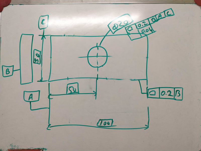
1. Keep datum feature A as is, but delete the all round 0.1 profile (it is partially redundant as the top and bottom faces of the part are also controlled with the all around profile in the other view). Replace it with a single flatness tolerance.
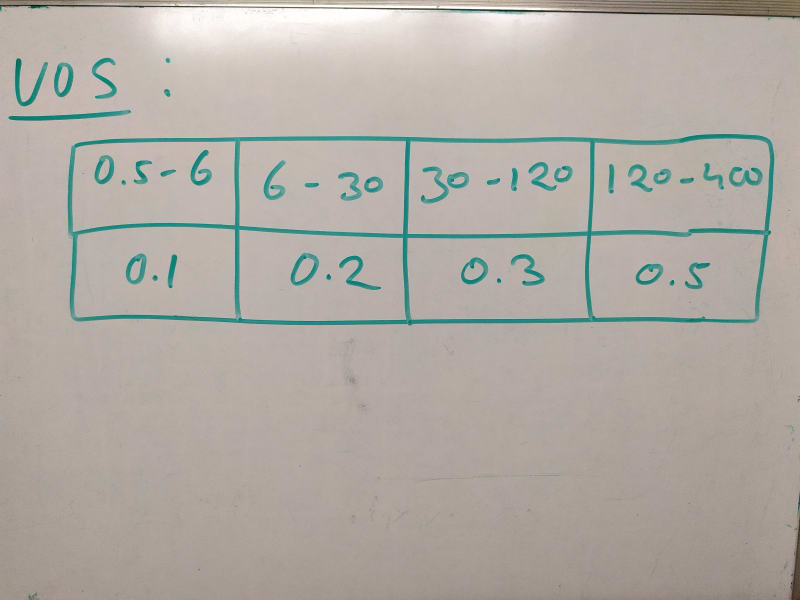
2. Keep datum feature B as is, but replace the position tolerance with perpendicularity as the hole does not have a location relationship to A. Also, I am curious where the 0.1 MAX requirement comes from. If it is justified from functional standpoint, put dia. 0.1 MAX in the same compartment as dia. 0(M), if the drawing is per Y14.5-2009 or 2018. If per 1994, leave it as is.
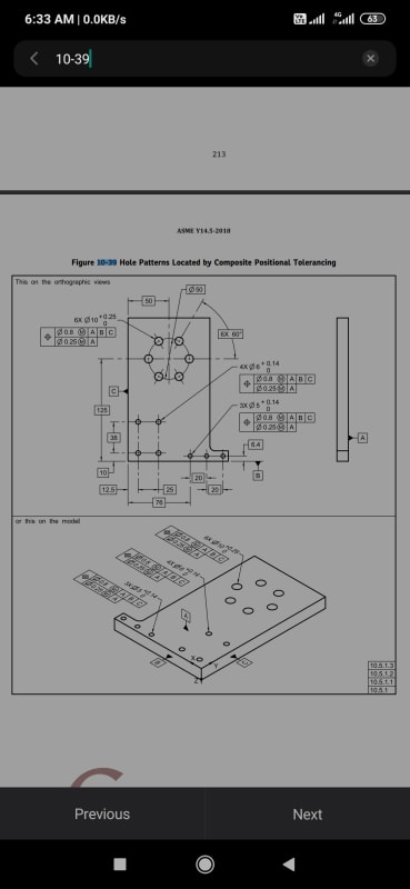
3. Define the pattern of four dia. 6.6 holes as datum feature C. Control it with position relative to |A|B(M)|. Remove C from the basic 56 width.
4. Each dia. 6.6 hole can still be defined as individual datum feature D to control position of the corresponding counterbore relative to |A|D(M)| individually and then refined with a perpendicularity callout relative to A, if needed.
5. Define the face opposed to A as datum feature E. Control it with profile relative to |A|. Make the dimension for the thickness of the part basic.
6. Keep datum feature F as is, but control it with position relative to |A|B(M)|C(M)| and refine with perpendicularity tolerance relative to E.
7. Define the width of the 6.3 slot as datum feature G and control it with position relative to |E|F(M)|.
8. Control the pattern of four dia. 5.5 holes relative to |E|F(M)|G(M)|.
Note: The MMB modifiers used in most of the callouts assume that there is no inteference between mating features in the entire assembly.


