Continue to Site

Eng-Tips is the largest engineering community on the Internet

Intelligent Work Forums for Engineering Professionals

  • Congratulations waross on being selected by the Eng-Tips community for having the most helpful posts in the forums last week. Way to Go!

Principle stress trajectory of beams 1

Status
Not open for further replies.

SKJ25POL

Structural
Mar 4, 2011
358

I appreciate helping me brush the rust.
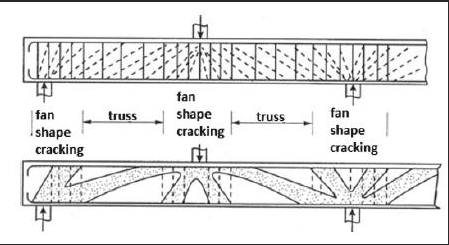
First, when the trajectory contours for a beam become straight line?
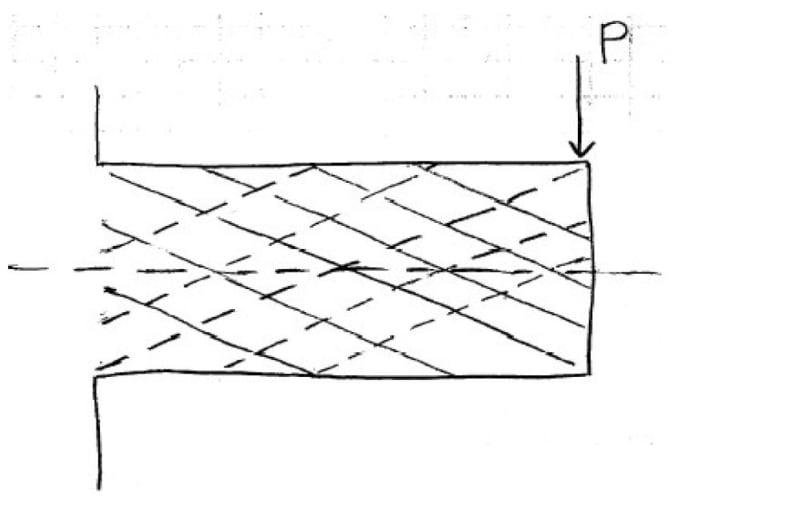
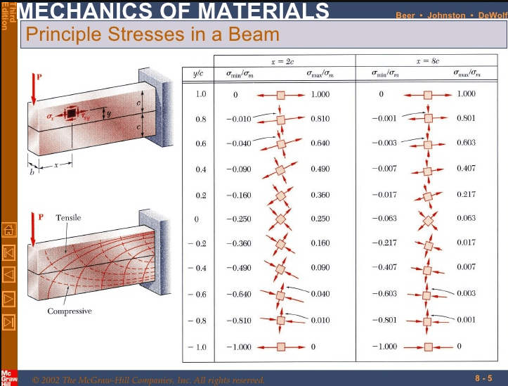
I thought no matter of type of loading (either uniform or point load), stress trajectory counters of a beam are always curves?
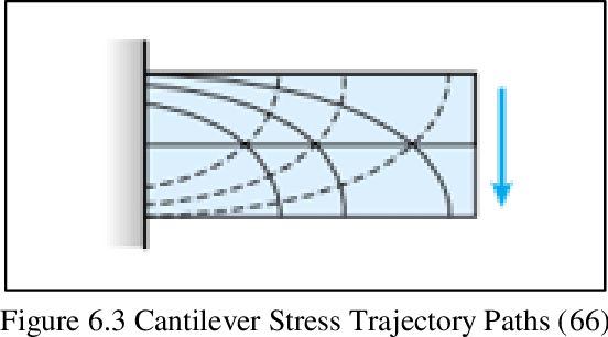
Second, Does the type of beam (cantilever or simply supported) make the curves straight line under any conditions?
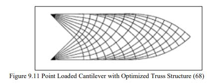
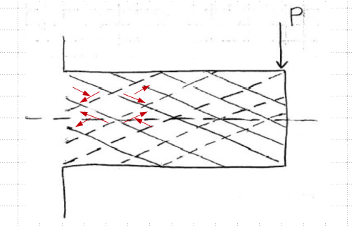
In a Canadian text book they draw a cantilever stress trajectory under a point load at free end with straight lines and same beam for uniform distributed all stress trajectories as curve?

Any pics, references that shed so light?

Thank you
 
Replies continue below

Recommended for you

Perhaps you could post the image you are referring to?

The cantilever under point load is similar to half a simply-supported beam under midspan load, which you'll probably find on the internet. The trajectories would be curved because the shear force is constant while the bending moment varies.

Trajectories would be straight for constant bending moment (zero shear).
 
steveh49 (Structural),
Thank you for your response.

So which one of below photos are correct. Both are cantilever with a point load, but one is straight line the other shows curve?
2_io4wpq.jpg


4_ksa3cx.png
 
The first one is the major shear stress. The bottom one is the principle stress.
 

r13 (Civil/Environmental)
Thank you for your response can you please explain little in details what's the first one?
Major shear stressed? Never heard of major shear stress!!! Just we had principle normal stresses didnt we?
Is major shear stress the Tau at each point?

Where can I learn on major shear stress? what book?

Thank you
 
I've seen this type of diagram. I call it major (not a correct term), because it is the maximum shear stress, which is half of the difference of the principal stress. See Mohr's circle for explanation.
 
r13 (Civil/Environmental)
Many thanks for response. My apology for bugging you but if you possibly remember where you might have seen it that would be great help.
I dug all my strength of material books and did not find this. If by the chance you recall what book may have address it, I would be really appreciated it.
 
I've not seen the exact diagram as yours. But this one shows the concept.

image_gho3oi.png
 
Anybody else can help please regarding the two figures or stress trajectory for a cantilever beam with a point load at the free end?

Which one is a correct and why? I am struggling to find what is the straight lines in the first figure?

I appreciate it you seen it in any reference book or text letting me know

Thank you all
Just is bothering not knowing what is it.
 
To me, the straight line sketch does not appear to be a principal stress diagram but, rather, an optimized truss representation derived from the the principle stress diagram. Check out the sketch below from this paper.

C01_jzsuop.jpg
 
to go back to the original question "when the trajectory contours for a beam become straight line?"

in the case of pure bending. if there is "any" shear then there'll be "some" curvature.

another day in paradise, or is paradise one day closer ?
 
See the orientation of τmax.

image_m4vdlf.png
 
r13 (Civil/Environmental),
I would like to thank you so much for your kind effort trying to help me.
Greatly appreciate it.
I agree that the curve contours are the right answer for the principle stress and I heard you mentioned the straight line is for zero shear9pure bending), however in a valid text book the straight lines was given and as all we know a cantilever with a point load at tip we don't have the pure bending state so the mystery is then why despite of not having pure bending for a cantilever with a point load why they have drawn a straight lines?????????
 
r13 (Civil/Environmental)

I am sorry I couldn't understand your last post on your best guess!
I see some red arrows, may I ask what are they representing?
Can you please explain a bit in details whats your "guess work"?
 
So which one of below photos are correct. Both are cantilever with a point load, but one is straight line the other shows curve?
Just a guess. May be the principal stresses due to flexure stresses are ignored in the first picture? Because, stress trajectories like picture 1 will be obtained for a pure shear case which results in equal and opposite principal stresses.
 
Could you post the description of the straight-line image given in the textbook? The caption as well as text that discusses it.
 
Well, this is a snap shot from a paper on compression field theory, a slab panel loaded in pure shear with constant axial stresses. This is vastly different than a cantilever beam with a varying bending moment but it does show the straight line cracks due to principal tensile stresses. I studied the topic for an assignment in my postgrad and only remember the basis concept (meaning: don't ask any complex question related to the topic :) ). But you can find vast text on the subject matter if you search the web.

image_uxkdyb.png
 
Can you please explain a bit in details whats your "guess work"?

It is plane stresses around a cut out element. Can you identify where are the shear stresses in the work, and how they correlate to your graph? Did you review any textbook on principal stresses and maximum shear stress, and their relationship?

You should post the source where you obtain the first graph, so we can check and help.
 
Status
Not open for further replies.

Part and Inventory Search

Sponsor