Tek-Tips is the largest IT community on the Internet today!

Members share and learn making Tek-Tips Forums the best source of peer-reviewed technical information on the Internet!

  • Congratulations TugboatEng on being selected by the Eng-Tips community for having the most helpful posts in the forums last week. Way to Go!

Principal stress and its angle at certain location of the model in pro mechanica

  • Thread starter Thread starter Chakkarabani Selvam
  • Start date Start date
C

Chakkarabani Selvam

Guest
Hi,

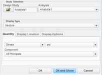
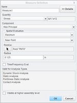
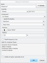
I would like to analyse principal stresses and its angle. can someone tell me how can I do it easily. The problem is that I need a principal stress at 2 points in model surface I have tried with dynamic query and graphs it did not work

I cannot obtain the values at my desired location.

Thank you.
 
Create datum points in the locations that you want the query and then create principal stress measures at those locations.

View attachment 6231
That will give you magnitude. You can also view magnitude and a visual direction from your results by creating a Vector display type result definition. Change the component to what kind of principal stress you desire. I also find that increasing the number of legend levels, using shaded vectors, and increasing the maximum length under the display options helps with the visibility.
View attachment 6230
I hope that helps.
 

Attachments

  • prncpl_strss1.JPG
    prncpl_strss1.JPG
    26.9 KB · Views: 9
  • prncpl_strss0.JPG
    prncpl_strss0.JPG
    33.8 KB · Views: 11
Hi,

Thank you so much for the reply... I have created the measure point but the study is not running. It shows me the error as integration mode something...

I think that is due to the point and the element nodes are not concurrent. Do you have any idea how to do different mesh size for a particular region of the beam.
 
Mechanica uses P-elements which minimize nodes but better define the part.
 
Sorry, I didn't see your reply earlier. Depending on what version of simulate you are running, when you create a measure, you can define the measure to be within a certain radius of the point. Another method would be to create an AutoGEM control hard point at the location of the point. I'm using Creo 2.0. You can also create maximum element size, min edge distances, or disperse node points but those are more difficult to match the location of your point. These methods will also allow you to increase/decrease mesh size for a particular area. You may have to define curves, etc. beforehand to create the regions you desire.
View attachment 6248
 

Attachments

  • measure.JPG
    measure.JPG
    34.4 KB · Views: 4

Part and Inventory Search

Sponsor

Back
Top