Eng-Tips is the largest forum for Engineering Professionals on the Internet.

Members share and learn making Eng-Tips Forums the best source of engineering information on the Internet!

  • Congratulations JStephen on being selected by the Eng-Tips community for having the most helpful posts in the forums last week. Way to Go!

Precast Wall Cast in Plate Design

Status
Not open for further replies.

LimeVta

Structural
Joined
Jun 27, 2021
Messages
3
Location
AU
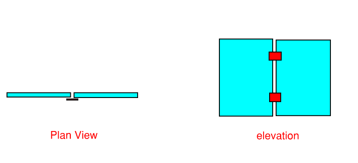
In my model, I leave gaps between precast panels. Now I have the analysis results and wondering how to design the typical precast cast-in plate between panels that are commonly seen in buildings as shown below.
Do we really need these cast-in plates since I model them separately in my analysis? (what happens if I don’t use these connections at all?) If yes, how do you design them, what forces should I design them to and why?

pn_i55lre.png


Can anyone please shed some light on this or provide some design examples? Thank you.
 
The normal strategy with shearwalls is to provide a laterally rigid building (as opposed to moment frames which absorb energy as they laterally flex). Linking the wall segments into a single wall is significantly more rigid. The design load would be VQ/I. If you leave them unconnected, how will prevent the floor slabs from transferring the shear between wall segments?
 
I guess the question to you is what do you want these panels to do? What is your design intent?

If the walls are shear walls, then two or three or four panels tied together are way, way more rigid than individual one-panel segments. It that your intent?

If each panel is designed be a separate shear wall, the anchorages at the base get more involved. It certainly can work, but it's not as efficient as a multi-panel wall acting as one.

If these are just cladding and not shear walls, the tie between walls is not nearly as important. Is that your intent?

Sometimes you have a big opening where the whole panel acts as a lintel. These plates might support gravity loads from adjacent panels. Is this what you have?

Make it act like you want it to act. That's the name of the game.


Thank you.
I understand that if panels are tied together it will be more rigid but more rigid means more seismic loads. So to clarify, I basically have the following scenarios that I try to avoid using or designing these stitch plates.
1. Stitch plate will fail it vertical shear flow, leading to wet joints. While the structure already works with separated panels instead of tied panels as one section (and that's why I put horizontal gaps between wall shells in my model)
2. Walls are required for gravity purposes and not critical for shear. The walls are quite long and have many corners, meaning it is hard to follow this 'shear flow' method since the I and Q is hard to calculate.

One last question, if you use these stitch plate between panels and design to vertical shear flow. Does that mean make these panels as one shell in your model instead of having gaps in between?
 
Status
Not open for further replies.

Part and Inventory Search

Sponsor

Back
Top