Continue to Site

Eng-Tips is the largest engineering community on the Internet

Intelligent Work Forums for Engineering Professionals

  • Congratulations cowski on being selected by the Eng-Tips community for having the most helpful posts in the forums last week. Way to Go!

Post-Tensioning Software

Status
Not open for further replies.

ajk1

Structural
Apr 22, 2011
1,791
What is the best software available today to use for post-tensioning, particularly as it relates to checking existing post-tensioned beams with unbonded tendons and bonded rebar? We want to determine the utilization ratio (Factored Moment / Resisting moment) when tendons break due (due to corrosion). We are checking to the Canadian CSA A23.3 Standard.

We have been using ADAPT PT but are looking to see what else is out there, and how people have found it. Some software that I have heard about is "SAFE" but the post-tensioning module is relatively expensive, (and I am not sure that it gives the utilization ratio) and RAM CONCEPT and perhaps SAFE has a p.t. module.

I am looking for something that is bug-free, or that if we find a bug the software marketer will not require us to pay for the next edition of the software in order to get the bug fixed.

 
Replies continue below

Recommended for you

ajk1 said:
Was the 25.5 feet clear span or centre-to-centre span? 5.5" thick p.t. slab (span/thickness = 55±) seems way too much, if the span is the clear span.

25.5' was centerline span. 12" dia. circular columns with 4' square inverted truncated pyramid capitals. Vibration was so excessive immediately after construction that W16 steel beams were attached (hung) from the underside of slab along both column line directions to reduce effects.

ajk1 said:
If one of those unencapsulated tendons should eventually fail due to corrosion or any other reason, it would be a significant public safety hazard, but I expect that you considered that.

Yes, but the nice thing with external tendons is that they are available for continuous and easy inspection along their whole length...but, vulnerable to vandalism...albeit that the vandals would only get to 'play' with such once in their lifetime!

ajk1 said:
I suppose the lack of fire protection could also be justified on the basis that it is a temporary emergency fix.

These particular strand tendons were somewhat of a new technology at the time (2002/3), greased and sheathed with a special intumescant coating that would provide a 30 minute FR, and given the open-air parking structure the AHJ was okay with the approach.

ajk1 said:
Would you have a photo of the anchorage for the ends of the tendons?

The four (4) tendons were double live-end stressed (300+ feet long structure), terminated with 2" thick x 10" square custom galv bearing plate with barrel chucks and wedges:

ANCHORAGE_jvopcw.jpg


Upon completion of the stressing, the tails were cut from one-end and a galvanized top-hat cap, grease filled, with rubber gasket, was stainless steel screw attached to the bearing plate. Similar to this thread back in April 2017 Link. Bearing plate was PU caulked around perimeter.

WAIKALANI_WOODLANDS_049_qxfweq.jpg


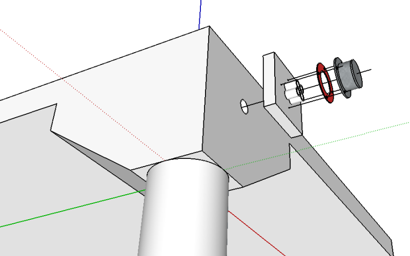
One of the live-ends was left with 4' long tails and the top-hat was modified to incorporate an extended galv tube with end cap to accommodate and protect the tails, so that when it came time to demolish the roof structure the external PT tendons could be de-stressed safely with ease, simply unbolt the extended end cap, and hydraulically de-stress the tendons, in multiple strokes. Somewhat like this sketch:

Capture_wkenfh.png
 
Those skimpy designs from the past certainly keep you busy, Ingenuity. But then, I expect that some of today's designs and construction practices will continue the tradition.
 
To Igenuity:

Very interesting.

Against what was the end plate placed? Was there a wall each end?

Did the intumescent coating have any moisture barrier properties to prevent condensation on the strand and corrosion?

Have you ever used an intumescent coating on strands where an inspection opening was chipped into the slab soffit and a removable cover plate installed (to allow future inspection on the strands)?
 
hokie66 said:
Those skimpy designs from the past certainly keep you busy, Ingenuity. But then, I expect that some of today's designs and construction practices will continue the tradition.

You speak the truth. Skimpy design coupled with on-site 'fixes' to tear/nicks/cuts to heat-sealed sheaths of the past that were done with tie-wired kraft paper, with no waterproofing to the roof deck, it is just a matter of time that they break down:

WAIKALANI_WOODLANDS_vzqjf0.jpg


The encapsulated PT system of today are far superior to that from the 60's through 80's, but some current site practices, with 'black-box' designs leave me questioning.

ajk1 said:
Against what was the end plate placed? Was there a wall each end?

No end/corner walls, just an existing corner column condition made up of 12" circular column and existing cut-off truncated pyramid capital - we cored horizontal drill 2" diameter holes thru caps, with obvert of hole flush with underside of slab. End details like this scaled sketch:

Capture_lnwm6b.png


The depth of the existing capital was substantial, but we did introduce an end eccentricity to accommodate the anchorage location.

There were a few parallel and perpendicular exterior walls and we made up custom steel deviators to take care of the harped tendon forces:

WAIKALANI_WOODLANDS_057_gtnpph.jpg


The perpendicular wall details was simply a CMU through-hole with steel deviator pipe to reduce masonry bearing stresses.

ajk1 said:
Did the intumescent coating have any moisture barrier properties to prevent condensation on the strand and corrosion?

The intumescent coating is integral with the strand/sheath system, and has the appearance and touch of a typical PT sheath (HDPE or Polypropylene), albeit a little thinner, and not as pliable. During the manufacture of the unbonded tendon (after the 7-wire strand manufacturing process), the bare strand goes through a grease bath, then immediately following, molten HDPE pellets are applied to create a thin HDPE sheath, that is water cooled, then a proprietary intumescent, woven-cloth reinforced FR material is applied immediately following, that bonds to the sheath, so their is no air space between the sheath and the FR, then an outer protective sheath is bonded to that. I think that is how is it manufactured - been more than 10 years since we last used the product.

On another project, FR was addressed by metal lathe and vermiculite plaster - awful product to hand apply, and the finished product looks awful too.

Have also used larger diameter continuous HDPE pipe/duct with tendons placed inside, then cement grouted the pipe. Looks way better than a plastered FR tendon, but in reality you don't actually get the FR along the full length especially at the deviation points where the tendon bears tight to the pipe/duct so no 'cementitious' cover here.
 
To Ingenuity - your detailed description and elegant sketch makes things very clear. Looks like a very well thought out and detailed job. Your "Ingenuity" name is well deserved. You should have won an award for this job, but I guess success is its own reward. Thanks very much.
 
ajk1 said:
You should have won an award for this job, but I guess success is its own reward.

Thank you, very nice of you.

This parking structure was part of a condominium association (you know, run like a political subcommittee, with 250 owners all with their agendas), so my older, cynical self is 'rewarded' when: 1) get paid 100% in a reasonable time frame, AND 2) don't get dragged into a legal suit.

All the best for your PT software research.
 
Status
Not open for further replies.

Part and Inventory Search

Sponsor